Remora - ethernet NVEM cnc board
29 Apr 2022 09:37 #241619
by Domi
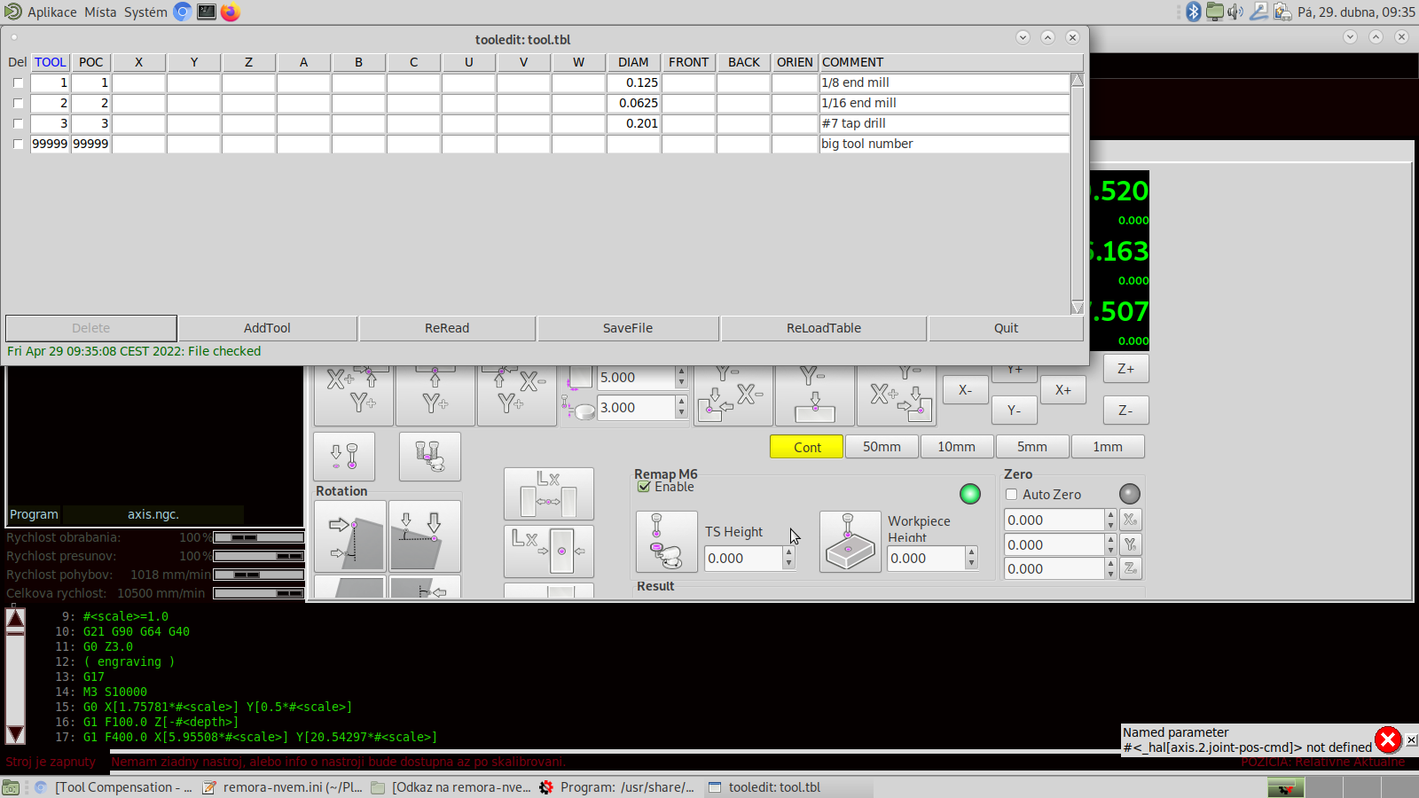
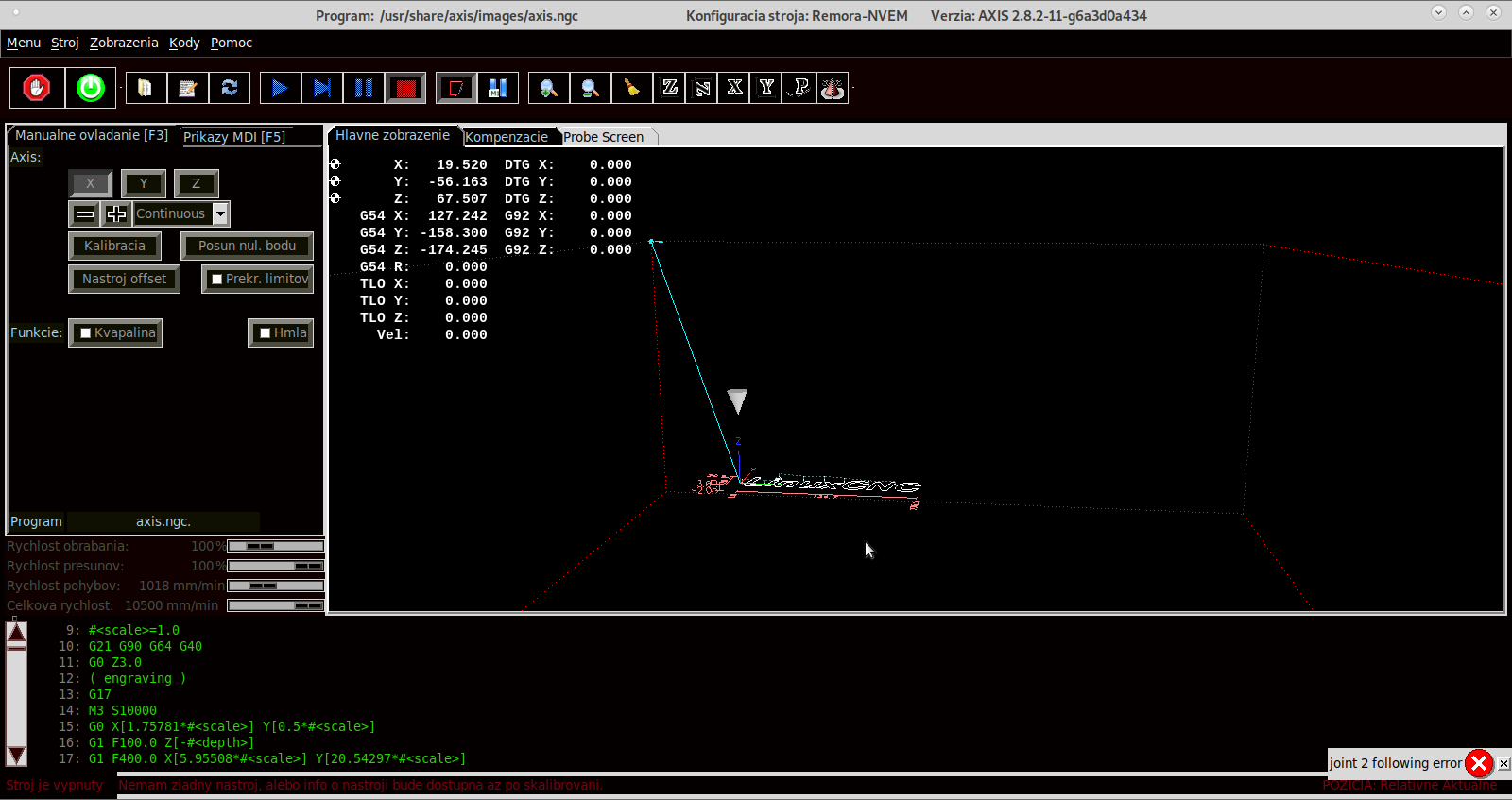 Hello. I ran almost everything. Air for probe touch sensor and so on. The spindle failed. Royka: Wouldn't you provide your file ini? And I have another problem that I can't solve. still has joint2 and max limit error. I've tried everything but I can't handle it. I send photos and files of halls and others. Thank you in advance for the advice.
Replied by Domi on topic Remora - ethernet NVEM cnc board
Attachments:
Please Log in or Create an account to join the conversation.
29 Apr 2022 09:39 #241621
by Domi
Replied by Domi on topic Remora - ethernet NVEM cnc board
I'm sorry. I don't know why it took more times.
Please Log in or Create an account to join the conversation.

29 Apr 2022 22:45 #241688
by scotta
Replied by scotta on topic Remora - ethernet NVEM cnc board
It may be possible using stm32duino ( github.com/stm32duino/Arduino_Core_STM32 ) which is based on STM32Cube, so the same HAL layer.Take a doubt, forgive me in advance if I'm asking a nonsense, because I'm learning all this about programming, I'm testing the esp32 with linux which by the way works very well, there we use the arduino ide to write the firmware, I wanted to know if here with the remora, it would be possible to use the arduino ide too or would that not be possible? I won a nvem to start my studies, I'm waiting for it to arrive to start the tests.
Please Log in or Create an account to join the conversation.
30 Apr 2022 14:31 #241713
by Domi
Replied by Domi on topic Remora - ethernet NVEM cnc board
???? This is an NVEM V2 board. Can someone please help with my problem? In fact, anyone who goes the route will need it. What I'm very grateful to Scott for. If I have everything done and functional then I will be happy to share the files for everyone. I'm beginning to understand paths and lines. But not yet at 100 percent. well thank you
Please Log in or Create an account to join the conversation.
30 Apr 2022 16:33 - 30 Apr 2022 16:56 #241721
by royka
Edit: didn't see the pictures, but still isn't it t a problem with the board/firmware. For the following error you could set the velocity of the joint higher then the axis velocity. Scotta explained that already to me in this topic, however I still had the following errors. The parameter errors I don't know. As far as I can see it's nothing from the ini or hal, perhaps in one of the other linked files "toplevel.py, one of the probescreen files, etc...", but better to ask these questions in the right section
Replied by royka on topic Remora - ethernet NVEM cnc board
This is nvem2 topic indeed. the problems you mention has nothing to do with the nemv2 board/firmware. As Scotta already told you there are other sections on this forum for these questions. In my ini file you won't find anything about the spindle, this information needs te be in your hal file, this info I've already posted. The max limit is the soft limit you set in the ini file under the axis and joints, but again this has nothind to do with the nvem2. It would be nice if you could keep this topic clean, so when people want to find info about Scotta his firmware for this board they could find it easily.???? This is an NVEM V2 board. Can someone please help with my problem? In fact, anyone who goes the route will need it. What I'm very grateful to Scott for. If I have everything done and functional then I will be happy to share the files for everyone. I'm beginning to understand paths and lines. But not yet at 100 percent. well thank you
Edit: didn't see the pictures, but still isn't it t a problem with the board/firmware. For the following error you could set the velocity of the joint higher then the axis velocity. Scotta explained that already to me in this topic, however I still had the following errors. The parameter errors I don't know. As far as I can see it's nothing from the ini or hal, perhaps in one of the other linked files "toplevel.py, one of the probescreen files, etc...", but better to ask these questions in the right section
Last edit: 30 Apr 2022 16:56 by royka.
Please Log in or Create an account to join the conversation.
30 Apr 2022 23:04 #241745
by scotta
Replied by scotta on topic Remora - ethernet NVEM cnc board
Domi,
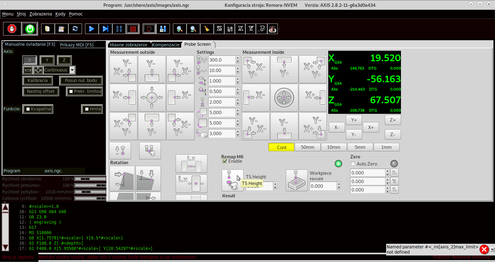
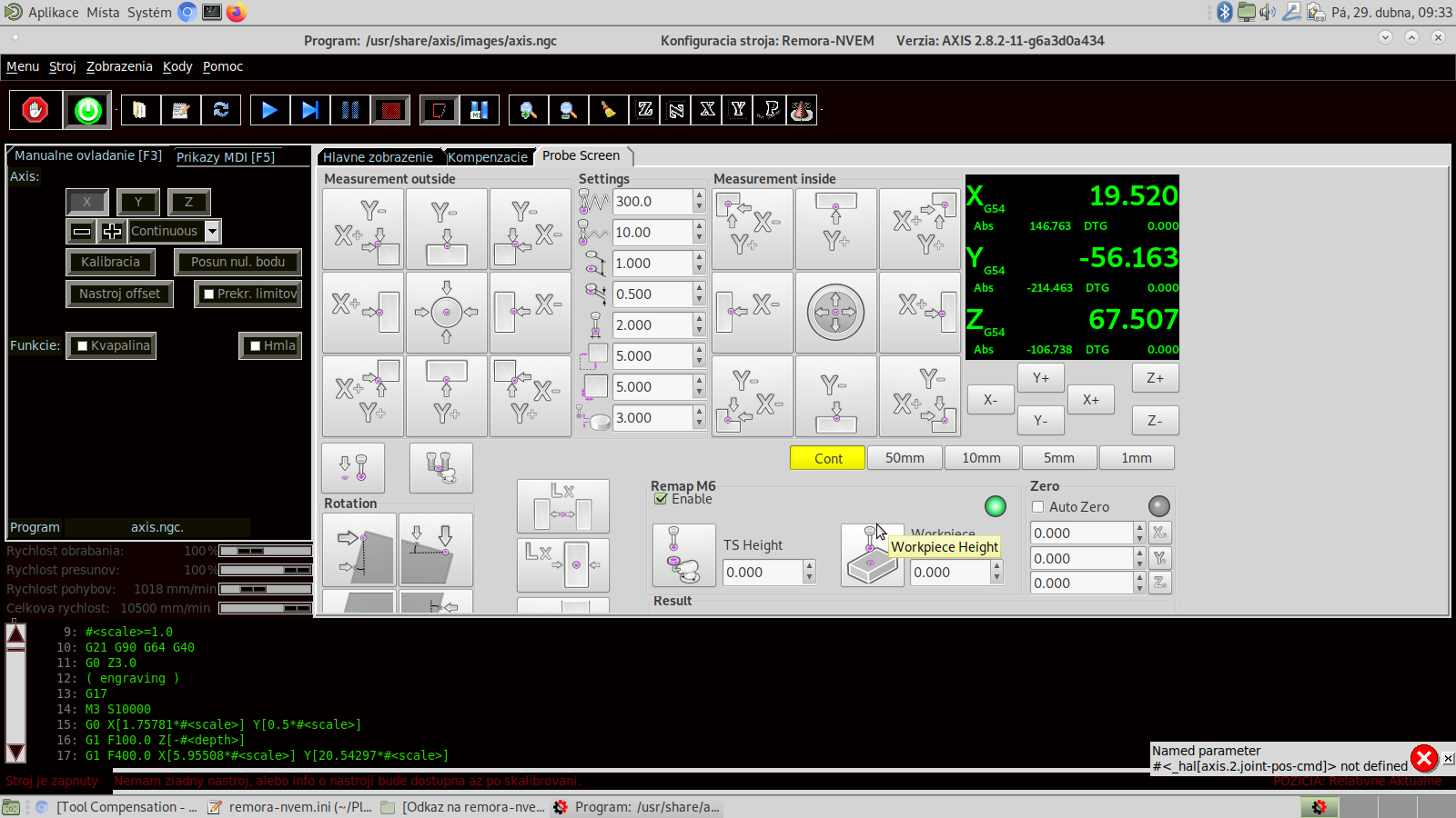
For [AXIS_2] MAX_LIMIT is not defined, this looks to be because of an old version probe_screen.py
forum.linuxcnc.org/gmoccapy/36973-error-...be-screen-v2?start=0
I'm guessing the _hal error is also due to an old probe screen of gladevcp using axis numbers rather than letters. Best to ask for help in those sections of the forum.
The following user(s) said Thank You: Domi
Please Log in or Create an account to join the conversation.
30 Apr 2022 23:09 #241746
by scotta
Replied by scotta on topic Remora - ethernet NVEM cnc board
Roy, FYI I'm still looking at the following errors. Something really strange going on somewhere as the errors are consistently the same magnitude. I could test by increasing the max following error so that the program would keep running. The same magnitude following error spike on different joints. Makes me think it's something to do with DDS accumulator over flow that Rafal observed in the other thread. Anyway, Thanks for your help and patience.
Please Log in or Create an account to join the conversation.
01 May 2022 10:37 #241790
by royka
Replied by royka on topic Remora - ethernet NVEM cnc board
Good to know that you've recognized the problem. I'm not a programmer or whatsover so maybe it's nonsense. But I was thinking, could it be an config error so it uses the internal oscillator? As the internal one is unstable according this site: www.jaybee.cz/software/stm32-hse-oscillator-stability-problem/ . Or as I've read some more problems about this board with the original firmware, maybe the external one being unstable? Because of a bad pcb design as seen on this site?: community.st.com/s/question/0D53W00001IB...-internal-oscillatorRoy, FYI I'm still looking at the following errors. Something really strange going on somewhere as the errors are consistently the same magnitude. I could test by increasing the max following error so that the program would keep running. The same magnitude following error spike on different joints. Makes me think it's something to do with DDS accumulator over flow that Rafal observed in the other thread. Anyway, Thanks for your help and patience.
Please Log in or Create an account to join the conversation.

01 May 2022 18:05 #241804
by fupeama
Replied by fupeama on topic Remora - ethernet NVEM cnc board
HI,
Can I ask for help?
I have 3axis nvem v2 card.
I am able....
Compile firmware in stm32cubeide.
Upload (compiled or downloaded ) firmware to card through st-link v2.
upload config.txt to storage space in card. rs232 say, that all is ok.
compile and install remora-eth.c
ping to card 10.10.10.10, ok
But... I cannot connect to card. Linuxcnc start independently on ip adress.
I try to changed ip for example to 10.10.10.11 or 192.168.1.1. in remora-eth.c. or disconnect card. result is same. linuxcnc start, I can see remora joint 0-7 but cmd feedback is death. following error on all joints.
there is some debug information on serial port or on linux when card is connect? I finished in IDLE state.
Thanks for hint
Martin
Please Log in or Create an account to join the conversation.
01 May 2022 19:03 #241806
by royka
Replied by royka on topic Remora - ethernet NVEM cnc board
On the serial monitor you should see it's loading the whole configuration, like this log:
## Entering SETUP state


1. Loading JSON configuration file from Flash memory


2. Parsing JSON configuration file
Config deserialisation - Deserialization succeeded

3. Configuring threads
Creating thread 40000
Creating thread 1000

4. Loading modules

Creating a std module
Creating an Ethernet communication monitoring module

Base thread object

X - Joint 0 step generator

Creating a std module
Creating Pin @
  port = GPIOE
  pin = 15
Creating Pin @
  port = GPIOE
  pin = 14

Base thread object

Y - Joint 1 step generator

Creating a std module
Creating Pin @
  port = GPIOE
  pin = 13
Creating Pin @
  port = GPIOE
  pin = 12

Base thread object

Z - Joint 2 step generator

Creating a std module
Creating Pin @
  port = GPIOE
  pin = 11
Creating Pin @
  port = GPIOE
  pin = 10

FHA
Make Digital Input at pin PD_12

Creating a std module
  Setting pin as No Pull
Creating Pin @
  port = GPIOD
  pin = 12

FHB
Make Digital Input at pin PD_13

Creating a std module
  Setting pin as No Pull
Creating Pin @
  port = GPIOD
  pin = 13

SRO
Make Digital Input at pin PB_14

Creating a std module
  Setting pin as No Pull
Creating Pin @
  port = GPIOB
  pin = 14

SJR
Make Digital Input at pin PB_15

Creating a std module
  Setting pin as No Pull
Creating Pin @
  port = GPIOB
  pin = 15

STOP
Make Digital Input at pin PD_8

Creating a std module
  Setting pin as No Pull
Creating Pin @
  port = GPIOD
  pin = 8

PROBE
Make Digital Input at pin PD_9

Creating a std module
  Setting pin as No Pull
Creating Pin @
  port = GPIOD
  pin = 9

INP3
Make Digital Input at pin PD_10

Creating a std module
  Setting pin as No Pull
Creating Pin @
  port = GPIOD
  pin = 10

INP4
Make Digital Input at pin PD_11

Creating a std module
  Setting pin as No Pull
Creating Pin @
  port = GPIOD
  pin = 11

INP5
Make Digital Input at pin PD_14

Creating a std module
  Setting pin as No Pull
Creating Pin @
  port = GPIOD
  pin = 14

INP6
Make Digital Input at pin PD_15

Creating a std module
  Setting pin as No Pull
Creating Pin @
  port = GPIOD
  pin = 15

INP7
Make Digital Input at pin PC_6

Creating a std module
  Setting pin as No Pull
Creating Pin @
  port = GPIOC
  pin = 6

INP8
Make Digital Input at pin PC_7

Creating a std module
  Setting pin as No Pull
Creating Pin @
  port = GPIOC
  pin = 7

INP9
Make Digital Input at pin PC_8

Creating a std module
  Setting pin as No Pull
Creating Pin @
  port = GPIOC
  pin = 8

INP10
Make Digital Input at pin PC_9

Creating a std module
  Setting pin as No Pull
Creating Pin @
  port = GPIOC
  pin = 9

INP11
Make Digital Input at pin PA_11

Creating a std module
  Setting pin as No Pull
Creating Pin @
  port = GPIOA
  pin = 11

INP12
Make Digital Input at pin PA_12

Creating a std module
  Setting pin as No Pull
Creating Pin @
  port = GPIOA
  pin = 12

INDEX
Make Digital Input at pin PC_15

Creating a std module
  Setting pin as No Pull
Creating Pin @
  port = GPIOC
  pin = 15

x100
Make Digital Input at pin PA_15

Creating a std module
  Setting pin as No Pull
Creating Pin @
  port = GPIOA
  pin = 15

x10
Make Digital Input at pin PC_10

Creating a std module
  Setting pin as No Pull
Creating Pin @
  port = GPIOC
  pin = 10

x1
Make Digital Input at pin PC_11

Creating a std module
  Setting pin as No Pull
Creating Pin @
  port = GPIOC
  pin = 11

ESTOP
Make Digital Input at pin PC_12

Creating a std module
  Setting pin as No Pull
Creating Pin @
  port = GPIOC
  pin = 12

Xin
Make Digital Input at pin PD_7

Creating a std module
  Setting pin as No Pull
Creating Pin @
  port = GPIOD
  pin = 7

Yin
Make Digital Input at pin PD_4

Creating a std module
  Setting pin as No Pull
Creating Pin @
  port = GPIOD
  pin = 4

Zin
Make Digital Input at pin PD_3

Creating a std module
  Setting pin as No Pull
Creating Pin @
  port = GPIOD
  pin = 3

Ain
Make Digital Input at pin PD_2

Creating a std module
  Setting pin as No Pull
Creating Pin @
  port = GPIOD
  pin = 2

Bin
Make Digital Input at pin PD_1

Creating a std module
  Setting pin as No Pull
Creating Pin @
  port = GPIOD
  pin = 1

Cin
Make Digital Input at pin PD_0

Creating a std module
  Setting pin as No Pull
Creating Pin @
  port = GPIOD
  pin = 0

WHA
Make Digital Input at pin PB_7

Creating a std module
  Setting pin as No Pull
Creating Pin @
  port = GPIOB
  pin = 7

WHB
Make Digital Input at pin PB_6

Creating a std module
  Setting pin as No Pull
Creating Pin @
  port = GPIOB
  pin = 6

OUT1
Make Digital Output at pin PC_3

Creating a std module
Creating Pin @
  port = GPIOC
  pin = 3

OUT2
Make Digital Output at pin PC_2

Creating a std module
Creating Pin @
  port = GPIOC
  pin = 2

OUT3
Make Digital Output at pin PB_8

Creating a std module
Creating Pin @
  port = GPIOB
  pin = 8

OUT4
Make Digital Output at pin PB_9

Creating a std module
Creating Pin @
  port = GPIOB
  pin = 9

OUT5
Make Digital Output at pin PE_0

Creating a std module
Creating Pin @
  port = GPIOE
  pin = 0

OUT6
Make Digital Output at pin PE_1

Creating a std module
Creating Pin @
  port = GPIOE
  pin = 1

OUT7
Make Digital Output at pin PE_2

Creating a std module
Creating Pin @
  port = GPIOE
  pin = 2

OUT8
Make Digital Output at pin PE_3

Creating a std module
Creating Pin @
  port = GPIOE
  pin = 3

OUT9
Make Digital Output at pin PC_13

Creating a std module
Creating Pin @
  port = GPIOC
  pin = 13

OUT10
Make Digital Output at pin PC_14

Creating a std module
Creating Pin @
  port = GPIOC
  pin = 14

Spindle PWM

Creating a std module

NVMPG

Creating a std module
Registering interrupt for interrupt number = 58
Creating NVMPG module
UART1 DMA configured

## Entering START state

Starting the BASE thread
Registering interrupt for interrupt number = 25
        power on Timer 1

        timer started

Starting the SERVO thread
Registering interrupt for interrupt number = 28
        power on Timer 2

        timer started

## Entering IDLE state
Please Log in or Create an account to join the conversation.
Time to create page: 0.489 seconds