Remora - ethernet NVEM cnc board
01 Apr 2022 21:11 #239018
by Domi
Replied by Domi on topic Remora - ethernet NVEM cnc board
I changed it as you wrote. How else can I change it?
Please Log in or Create an account to join the conversation.
01 Apr 2022 21:13 #239019
by Domi
Replied by Domi on topic Remora - ethernet NVEM cnc board
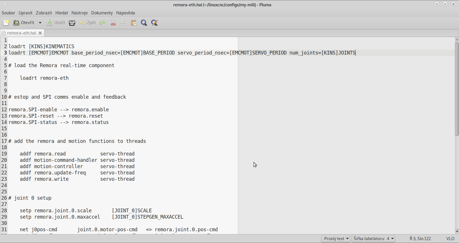
Attachments:
Please Log in or Create an account to join the conversation.
01 Apr 2022 21:16 - 01 Apr 2022 21:17 #239020
by royka
Replied by royka on topic Remora - ethernet NVEM cnc board
Haha i meant change remora.SPI-enable to remora.enable.
Here is the file as how I meant:
raw.githubusercontent.com/royka1/Remora/...a-eth/remora-eth.hal
Here is the file as how I meant:
raw.githubusercontent.com/royka1/Remora/...a-eth/remora-eth.hal
Last edit: 01 Apr 2022 21:17 by royka.
Please Log in or Create an account to join the conversation.
01 Apr 2022 21:35 #239021
by Domi
Replied by Domi on topic Remora - ethernet NVEM cnc board
How did you comment on joint 3? Now it shows me a joint 3 scale not found error
Please Log in or Create an account to join the conversation.

01 Apr 2022 21:38 #239022
by scotta
I also took a copy of the flash before installing Remora but I could not get the board to work with Mach3 again after restoring the original firmware. I tried to figure out what the mystery chip was by decompiling the firmware, but to no luck.
Replied by scotta on topic Remora - ethernet NVEM cnc board
Thanks for the work to figure out the mystery chip and as you say it must be a single wire EEPROM. Most likely used to give some form of feature enablement / protection. Maybe the number of axis that the board can have.Before I flashed the NVEM with the Remora firmware I created an image of the stock software also, so I have one if its needed. I did buy my board about a year ago and it says NVEMV2 on it so i believe it is a version 2 board, and I don't know how different they are.
I do have the mystery chip, although it is rotated from Scott's board and the power and ground pins are switched. The three connected pins are the same as Scott's diagram. Scott, when you tested the PA_3 pin do you remember if the ST-Link was connected? To be clear by connected I mean having pushed the "connect" button on the programmer, and disconnected meaning plugged in and powered up, but without connecting, or having pushed "disconnect" on the programmer. While the ST-Link was connected PA_3 stayed near ground, but when I disconnected the ST-Link I discovered a 3.75 Mhz square wave on the PA_3 pin. As soon as you connect the programmer the square wave stops, and it restarts on disconnect.
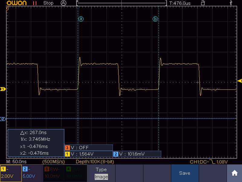
After the disconnect button is pushed or the device is initially powered on the PA_5 pin seems to go low for a short pulse, wait ~0.3 seconds, then host short burst of communication. The PA_4 pin goes low for this brief pause, and then returns high. This initial pulse (before the apparent communication) is when the PA_3 pin starts the 3.75 Mhz signal.
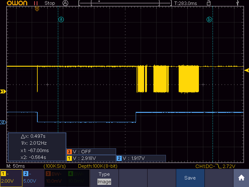
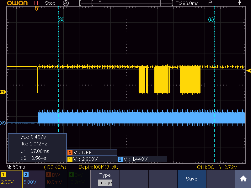
It appears that pin 5 is a single wire communication line. I'm not sure what it is but it appears to be high or low for multiples of 100 microseconds.
When I flashed the Remora firmware the signals all stopped. PA_4 and PA_5 remain high, and PA_3 remains low so whatever it is it's at least initiated by the processor. I'm not sure what to make of all this, but hopefully this will help.
I also took a copy of the flash before installing Remora but I could not get the board to work with Mach3 again after restoring the original firmware. I tried to figure out what the mystery chip was by decompiling the firmware, but to no luck.
Please Log in or Create an account to join the conversation.
01 Apr 2022 21:41 #239023
by royka
Replied by royka on topic Remora - ethernet NVEM cnc board
@Domi I sent you an example, how hard can it be? You should really just use GRBL, I've explained everything so many time and you still don't get it
Please Log in or Create an account to join the conversation.
01 Apr 2022 21:44 #239024
by scotta
github.com/scottalford75/Remora/tree/dev...igSamples/remora-eth
It is setup for 4 axes for a 3D printer. You will see in the INI file the config for 4 axes.
Over the weekend I'll upload my latest NVEM config (without spindle). as you found out the reference to SPI has been removed.
Great to see that you are determined to get it running, You are very very close.
Scott
Replied by scotta on topic Remora - ethernet NVEM cnc board
Hi, have a look at the config sampleHow did you comment on joint 3? Now it shows me a joint 3 scale not found error
github.com/scottalford75/Remora/tree/dev...igSamples/remora-eth
It is setup for 4 axes for a 3D printer. You will see in the INI file the config for 4 axes.
Over the weekend I'll upload my latest NVEM config (without spindle). as you found out the reference to SPI has been removed.
Great to see that you are determined to get it running, You are very very close.
Scott
Please Log in or Create an account to join the conversation.
01 Apr 2022 21:47 - 01 Apr 2022 21:47 #239025
by scotta
Replied by scotta on topic Remora - ethernet NVEM cnc board
The error you were getting is caused by the HAL file not finding the corresponding parameter in the INI file. You need to maintain and align both the HAL and INI files for the number of axes you have..
Last edit: 01 Apr 2022 21:47 by scotta.
Please Log in or Create an account to join the conversation.
01 Apr 2022 21:53 #239026
by Domi
Replied by Domi on topic Remora - ethernet NVEM cnc board
Royka: I copied your file and kept making a mistake for joint 3. Probably because it's a mistake in the file.
Scott: Thank you. yes close and at the same time so far: D
Scott: Thank you. yes close and at the same time so far: D
Please Log in or Create an account to join the conversation.
01 Apr 2022 21:58 #239027
by Domi
Replied by Domi on topic Remora - ethernet NVEM cnc board
scotta: yes that's what I meant. The 4th axis must be set in the inore fileThe error you were getting is caused by the HAL file not finding the corresponding parameter in the INI file. You need to maintain and align both the HAL and INI files for the number of axes you have..
Please Log in or Create an account to join the conversation.
Time to create page: 0.721 seconds