7i97 + 7i76D with Mesa Configuration Tool

18 May 2022 16:37 #243282
by andypugh
Simpler would be to use a resolver for the spindle too. That's what my machines have done.
I would suggest adding a 7i44 and 7i84 too. And maybe a 7i73 for the control panel.
Replied by andypugh on topic 1980 Cinturn 1212u Cincinnati Milacron refit
5i24 is a lot cheaper and a bit more compact. And I am using it with a 7i49. The spindle encoder could connect to one of the other ports with a 7i33 (though it seems overkill) or, with care, directly to the header.If you are gonna keep the resolvers, I have a Mesa resolver board with about 80 hours on it, I’ll sell it to ya for $120 and give you a hal file and ini for resolvers to get you started. A 7i49( I think ) needs a 5i23 to hold the resolver software.
Simpler would be to use a resolver for the spindle too. That's what my machines have done.
I would suggest adding a 7i44 and 7i84 too. And maybe a 7i73 for the control panel.
Please Log in or Create an account to join the conversation.

18 May 2022 17:07 #243284
by JR1050
Replied by JR1050 on topic 1980 Cinturn 1212u Cincinnati Milacron refit
Agreed. The 5i24 wasn’t available when I did the retro on my now scrapped Brown and Sharp. I find the 7i84 to be much easier the the 7i37 due to the screw type terminal blocks. Seems like I used a 5i23, 7i49, 7i44 , 7i33, 7i84 and a 5i20. I had 3 axis of resolvers and 4 of encoders. The 5i20 handled the encoders and opto I/o and the 5i23 the resolvers and serial I/o. It would have been easier to use the 5i23 with the resolver board, encoder board and 7i44. Patch the 7i84 for the pendent to the 7i44 and use a 7i90 in “ just I/o “ for the opto racks. Lesson learned.
Please Log in or Create an account to join the conversation.
- smc.collins
- Offline
- Platinum Member
-

Less
More
- Posts: 655
- Thank you received: 109
18 May 2022 21:08 #243295
by smc.collins
Replied by smc.collins on topic 1980 Cinturn 1212u Cincinnati Milacron refit
pulled for encoders, these resolvers are a bit nonstandard, so instead of wasting a ton of time, I am putting encoders on as we speak
Please Log in or Create an account to join the conversation.
- smc.collins
- Offline
- Platinum Member
-
Less
More
- Posts: 655
- Thank you received: 109
25 Jun 2022 18:33 #245873
by smc.collins
Replied by smc.collins on topic 1980 Cinturn 1212u Cincinnati Milacron refit
I have been struggling to figure out exactly which drives my machine has, operationally they look identical to the gettys drives. However getting them to work is looking very difficult.
Also the reliance V*S spindle drive is bonkers. this thing is doing way more stuff than I need it to do. I just need it to go forward and backwards, that is all I need it to do
If you have any input on how to actually get this stuff to work, that would be phenomenal. I am at the point where it is do or die, I either make this garbage work or I replace it all. Financially at the moment that would leave the machine sitting for a extended period of time doing nothing but eating space.
this manual is all I have been able to find regarding the arcamatic 900 type systems, but it is light on explaining exactly how the driver interact with the control system
drive.google.com/file/d/1ljKkqcASbKIMjf9...mM4/view?usp=sharing
Please Log in or Create an account to join the conversation.
- tommylight
-

- Away
- Moderator
-

Less
More
- Posts: 17771
- Thank you received: 5907
25 Jun 2022 22:56 #245888
by tommylight
Replied by tommylight on topic 1980 Cinturn 1212u Cincinnati Milacron refit
Ouch, that is a loooong and heavy document, my mouse is still dizzy from scrolling through it! ")
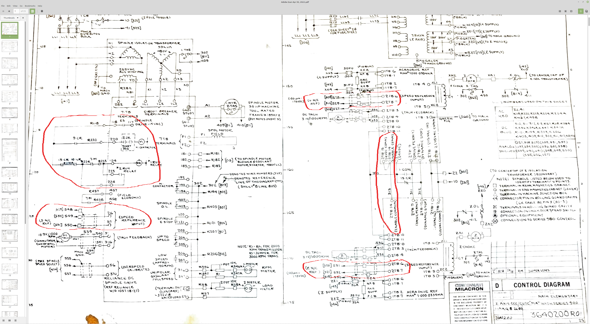
I did find the spindle block diagram, but i can hardly read anything in it on a 28" screen.
The schematic you uploaded earlier, did you check if they are similar to your machine?
We need "close enough", does not have to be exact, but as a starting point:
0-can you power on the machine?
1-can you enable the drives as they are now?
2-if you can, find the "speed reference" wires/connector for any drive or spindle, preferably spindle as it will not break anything if it goes full blast while testing.
3-take a small 1.5V battery and connect the "speed reference" wires to it, try both polarities and see if the spindle direction changes.
4-if you can not enable them, find the enable, for the spindle it is a bit murky, for the drives it seems they should be tied to ground, but do use a resistor of at least 100 Ohm while testing it.
Attached, marked parts/pins to find on the actual machine.
Basically, that is all you need for a retrofit as a starting point.
If there is a possibility of detaching servo motors while testing and tuning, it is a very good idea.
Attachments:
Please Log in or Create an account to join the conversation.
- smc.collins
- Offline
- Platinum Member
-
Less
More
- Posts: 655
- Thank you received: 109
26 Jun 2022 12:35 - 26 Jun 2022 12:36 #245914
by smc.collins
Replied by smc.collins on topic 1980 Cinturn 1212u Cincinnati Milacron refit
by lookin at the schematics and what's on the drives themselves, the circuits do not actually match up.
Lets look at the slide drives X and Z
we have 120vac on terminals 1 & 2 check
tach on terminals 3&4 check
we have our velocity commands on terminals 6 & 7
No here's where things get really fucking stupid
10 and 11 are motion enable per the drive labeling on the housing, those are wired to constantly be enabled btw, I am not sure this was a good design choice on the part of cincinatti if the following things are true
things are about to get VERY DUMB
terminal 13 is essentially the emergency braking function, is is controlled by a coil relay which is illustrated as being normally closed, if you bring the 24v of NC voltage to terminal 13, the drives go full power and the braking resistor takes a bunch of heat. I suspect that this is either part of Estop OR the controls were using this to decelerate the machine. not really sure why the hell you would do this with a normally close relay however. Seems like you would risk destroying the drives if the wire for the power supply got loose. ohhh, but that wire from the 13-cr doesn't go directly through the relay, it goes to other contactor relays, yay, not documented
even dumbers
terminal 9 is most definitely not a drive permit afaict, and when it gets power then the contactor close for 1-con, if I bring power to terminal 9 the motor hum, and show voltage. that power being 24v from closing the contactor to enable power to the RCS
it was at this point, one of the RCS in the Z drive failed, despite me verifying the voltages are the tach input were correct and the inputs were at 0v. I have a spare RCS so I can repair it
the problem is that whoever designed this machine, was either a genius, or the most incompetent electrical engineer in history. I lean towards the ladder. This thing has no less then 100 points of estop connections. First off, if you actually need the Estop, shits already in too late mode, secondly, the correct way is to watch for deviation from commanded motion. third the estop circuit should turn off the contactors and enable any braking in the machine, the spindle and the X have brakes, it didn't need to be the type of circuit it is, a simple relay to shut off the contactors and turn on the brakes would have been more than sufficient. it would have also been safer and more reliable to build the Estop this way. Very much has a design by committee look to it where legal was obsessing over imaginary safety concerns or the engineering team was exceptionally paranoid and there was poor leadership. I suspect a mix of both.
Lastly and most importantly, it looks like whoever did the engineering work, basically tried to design a analog switch gear driven CNC machine, and this thing had a very powerful for it's time intel based computer with a gui and a monitor. It wasn't lacking for computing power.
This machine was definitely in the class of what I would call electrically /functionally fragile. Meaning it had far to many places where failures even benign ones would cause the machine to be inop or cause it to have catastrophic malfunctions
I gutted ALL of the controls wiring last night, time to start over. I think I can get the spindle drive to work, maybe, it is a reliance drive, the documentation is kinda sketchy, I will attach that PDF which is again, not exactly related to my drive but it is all I have. I am going to just rebuild the entire enable circut and put a 500 ohm 10 resistor across the drive outputs, that should get the RCS transformer to balance and show voltage so I can test it without damaging the machine.
Push comes to shove, I am all about replacing these drives, the motor look very robust however. but if I can't get these drives working soon, I will be looking to replace the drives and if that proves undoable, AC servos it will be.
Last edit: 26 Jun 2022 12:36 by smc.collins.
Please Log in or Create an account to join the conversation.
- smc.collins
- Offline
- Platinum Member
-
Less
More
- Posts: 655
- Thank you received: 109
26 Jun 2022 13:44 - 26 Jun 2022 13:54 #245924
by smc.collins
Replied by smc.collins on topic 7i97 + 7i76D with Mesa Configuration Tool
spindle documentation, I have a V*S drive in the 30hp or 200 amp range, I am shopping for the exact manual, unfortunately the model and serial number info appears to be missing from my drive.
drive.google.com/file/d/1pYF7jGFJXQZDkMJ...vvs/view?usp=sharing
drive.google.com/file/d/1pYF7jGFJXQZDkMJ...vvs/view?usp=sharing
Last edit: 26 Jun 2022 13:54 by smc.collins.
Please Log in or Create an account to join the conversation.
28 Jun 2022 22:21 #246117
by andypugh
Replied by andypugh on topic 7i97 + 7i76D with Mesa Configuration Tool
Are these PM DC motors, or field-coil type? The drive looks like it might work with both.
Please Log in or Create an account to join the conversation.
- smc.collins
- Offline
- Platinum Member
-
Less
More
- Posts: 655
- Thank you received: 109
29 Jun 2022 01:49 #246124
by smc.collins
Replied by smc.collins on topic 7i97 + 7i76D with Mesa Configuration Tool
afaict, they are PM not shunt wound. I did find a set of DC drives that look as if they will work. I am digging further into this shortly. I believe I can make the reliance spindle drive work, but Cincinnati didn't even follow the documentation from Reliance on how to make that work either,
Honestly, I am going to beat this thing into submission enough to get it producing parts and as fast as I can afford to, replace ALL of the servos and drives in it with modern AC stuff. thankfully nothing I am making will have a tolerance tight enough to be to worried about it.
Honestly, I am going to beat this thing into submission enough to get it producing parts and as fast as I can afford to, replace ALL of the servos and drives in it with modern AC stuff. thankfully nothing I am making will have a tolerance tight enough to be to worried about it.
Please Log in or Create an account to join the conversation.
Moderators: piasdom
Time to create page: 0.116 seconds