- Configuring LinuxCNC
- Advanced Configuration
- Anybody working on Tool-Coordinate kinematics to Robots?
Anybody working on Tool-Coordinate kinematics to Robots?
- Aciera
-
 Topic Author
- Offline
- Administrator
-

Less
More
- Posts: 4736
- Thank you received: 2123
29 Feb 2020 10:02 - 07 Mar 2020 07:57 #158798
by Aciera
[Solved] Anybody working on Tool-Coordinate kinematics to Robots? was created by Aciera
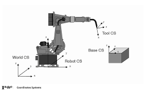
Is there anybody out there who is working on a Kinematics for Tool-Coordinate movements for a 6-axis robot manipulator?
I'm working on a config for a Mitsubishi melfa robot (forum.linuxcnc.org/10-advanced-configura...th-simulation#158467).
Since it is based on dgarrett's switchkins branch (www.panix.com/~dgarrett/stuff/s_kins_guide.txt) and genserkins it is a generic config that can be adjusted using modified DH-Parameters to be used for other robots.
My aim is to be able to control a robot manipulator as pick-and-place unit for example for machine tending.
The new switchkins-branch has made it possible to switch between coordinated moves in a cartesian system (XYZABC) and Joint-moves (J1,J2,J3,J4,J5,J6) inside GCode using M-codes. dgarrett has now included a template to create additional kinematics (forum.linuxcnc.org/10-advanced-configura...file?start=10#158757)
Now we can program moves in GCode to different poses that can't be reached using coordinated moves alone due to singularities in the system. Another prerequisite for pick and place is the handling of general purpose inputs and outputs in GCode which can be achieved using M62 .. M68 and conditional programming using O-codes. So LinuxCNC now covers the fuctionality needed to be used as a controller for industrial robots beyond milling foam.
One feature that is still missing is the ability to command a move in the tool-coordinate system that originates in the hand and follows the hand rotation. This is important when working with asymmetrical tools like grippers, welding torches or spray guns.
The math involved is not terribly difficult really just two more matrix multiplications. However C-programming is not my strongest point and I am struggling with the impementation.
So if anybody is or has been working on this please share!
Attachments:
Last edit: 07 Mar 2020 07:57 by Aciera.
Please Log in or Create an account to join the conversation.
- bbsr_5a
- Offline
- Platinum Member
-

Less
More
- Posts: 544
- Thank you received: 106
29 Feb 2020 16:48 #158823
by bbsr_5a
Replied by bbsr_5a on topic Anybody working on Tool-Coordinate kinematics to Robots?
the puma kinetics as of the AXIS/SIM Vismach file will do this job for you just give it a try
Please Log in or Create an account to join the conversation.
- Aciera
-
Topic Author
- Offline
- Administrator
-
Less
More
- Posts: 4736
- Thank you received: 2123
01 Mar 2020 09:11 #158874
by Aciera
Replied by Aciera on topic Anybody working on Tool-Coordinate kinematics to Robots?
bbsr_5a: thanks for the message!
I have created a config using pumakins. However I find no possibility to move in Tool-Coordinates, it always moves in World-Coodinates (the coordinates at the base of the arm). In Tool-coordinates the path would have to follow the red line of the coordinate system attached to the tool tip. :
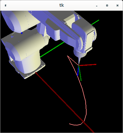
I have created a config using pumakins. However I find no possibility to move in Tool-Coordinates, it always moves in World-Coodinates (the coordinates at the base of the arm). In Tool-coordinates the path would have to follow the red line of the coordinate system attached to the tool tip. :
Attachments:
Please Log in or Create an account to join the conversation.
- thang
- Offline
- Elite Member
-

Less
More
- Posts: 196
- Thank you received: 11
02 Mar 2020 03:48 #158935
by thang
Replied by thang on topic Anybody working on Tool-Coordinate kinematics to Robots?
Hmm, i'm not understanding your tool-coordinate system.Is it mean move robot end effector CS to tool center point (because dimension of tool always greater than 0 and orientation of tool often difference )?
Please Log in or Create an account to join the conversation.
- Aciera
-
Topic Author
- Offline
- Administrator
-
Less
More
- Posts: 4736
- Thank you received: 2123
03 Mar 2020 07:21 - 03 Mar 2020 07:25 #159066
by Aciera
Replied by Aciera on topic Anybody working on Tool-Coordinate kinematics to Robots?
The tool-coordinate system is used to move along the axis' of the tool attached to the robots wrist like this:
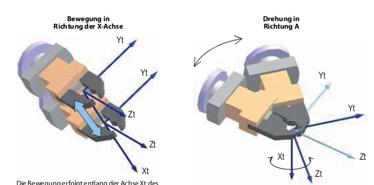
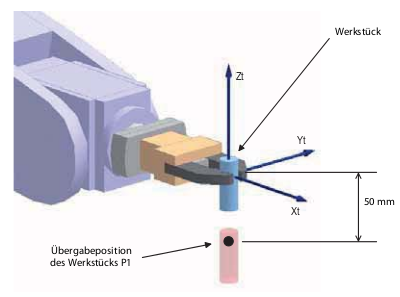
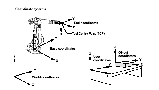
It is very useful to orient a workpiece when working in pick-and-place operations. Just suppose the z-axis of the workpiece in the following images is NOT parallel to any world-coordinate axis' that would make programming this move very difficult:

I have remapped G91.2 to command a incremental move in the x, y, z direction of the tool:
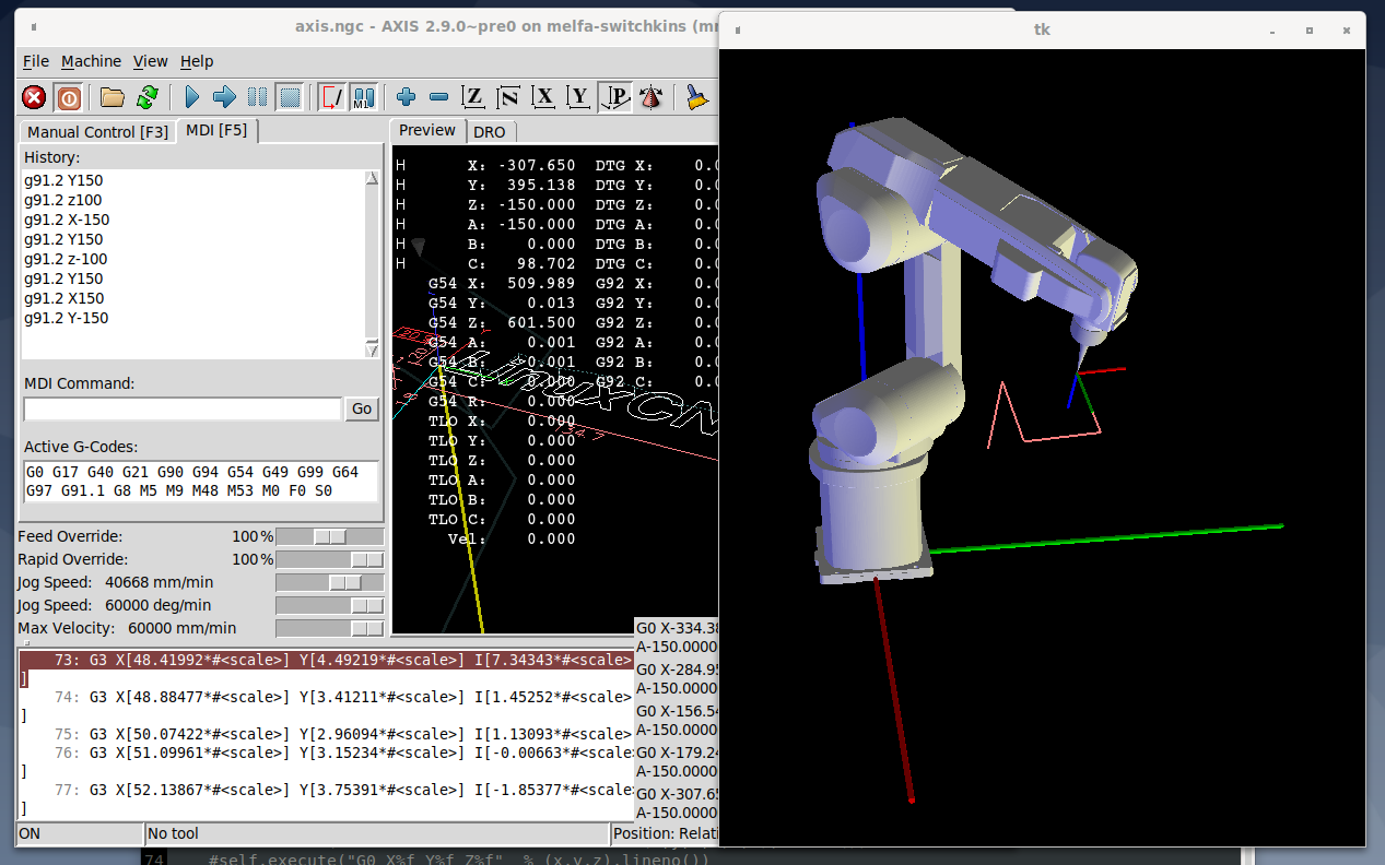
I hope to add the rotations a,b, c as well but that has turned out to be quite a bit more complicated.
And yes the geometry and tool-center-point of the tool has to be programmed in [X,Y,Z,A,B,C] values.
It is very useful to orient a workpiece when working in pick-and-place operations. Just suppose the z-axis of the workpiece in the following images is NOT parallel to any world-coordinate axis' that would make programming this move very difficult:
I have remapped G91.2 to command a incremental move in the x, y, z direction of the tool:
I hope to add the rotations a,b, c as well but that has turned out to be quite a bit more complicated.
And yes the geometry and tool-center-point of the tool has to be programmed in [X,Y,Z,A,B,C] values.
Last edit: 03 Mar 2020 07:25 by Aciera.
Please Log in or Create an account to join the conversation.
- andypugh
-

- Offline
- Moderator
-

Less
More
- Posts: 19875
- Thank you received: 4642
05 Mar 2020 14:35 #159262
by andypugh
Replied by andypugh on topic Anybody working on Tool-Coordinate kinematics to Robots?
I have seen some kins that use the W-axis as the tool-point Z.
I don't think I have seen any that use U and V for tool-point X and Y, but I can imagine that might be possible.
This might be simpler than switching kinematics.
I don't think I have seen any that use U and V for tool-point X and Y, but I can imagine that might be possible.
This might be simpler than switching kinematics.
Please Log in or Create an account to join the conversation.
- Aciera
-
Topic Author
- Offline
- Administrator
-
Less
More
- Posts: 4736
- Thank you received: 2123
05 Mar 2020 18:04 - 05 Mar 2020 18:21 #159269
by Aciera
Replied by Aciera on topic Anybody working on Tool-Coordinate kinematics to Robots?
I only switch kinematics to switch from World-cartesian movements to joint movements. For cartesian movements in tool-coordinates I thought it was nesserary to use yet another kinematic. Then I realized that it was possible to achieve that simply with a remap and a python script. That works fine, at least with linear movments. I can now use G91.2 x y z and the tool moves as an incremental move from the current position along the tool coordinate system.
Then I also wanted to be able to rotate the tool around the axis Y and Z of the tool coordinates (red in the image below). Rotation around X(x'')-Axis is the A-value in LinuxCNC but B rotates around y''(y') of the green coordinate system and C-value rotates the tool around the z'(z)-axis of the world-coordinate system.
Now I'm stuck at trying to figure out an algorithm to change the A,B and C-angles in such a way that the tool-coordinate system (red) rotates around its own Y or Z axis. I've searched for hours but haven't found a solution. So if anybody knows how to do that, please advise!
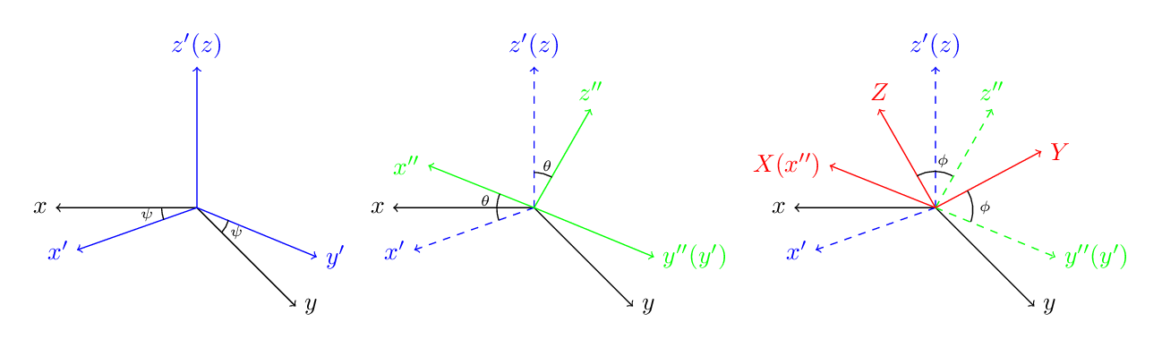
Black: World-coordinates (robot-base), Blue and Green: intermediate coordinate-systems, , Red: tool-coordinates (robot-tool)
Then I also wanted to be able to rotate the tool around the axis Y and Z of the tool coordinates (red in the image below). Rotation around X(x'')-Axis is the A-value in LinuxCNC but B rotates around y''(y') of the green coordinate system and C-value rotates the tool around the z'(z)-axis of the world-coordinate system.
Now I'm stuck at trying to figure out an algorithm to change the A,B and C-angles in such a way that the tool-coordinate system (red) rotates around its own Y or Z axis. I've searched for hours but haven't found a solution. So if anybody knows how to do that, please advise!
Black: World-coordinates (robot-base), Blue and Green: intermediate coordinate-systems, , Red: tool-coordinates (robot-tool)
Attachments:
Last edit: 05 Mar 2020 18:21 by Aciera.
Please Log in or Create an account to join the conversation.
- Aciera
-
Topic Author
- Offline
- Administrator
-
Less
More
- Posts: 4736
- Thank you received: 2123
07 Mar 2020 07:57 #159380
by Aciera
Replied by Aciera on topic Anybody working on Tool-Coordinate kinematics to Robots?
I have found a solution for this and will update the files in the other thread.
Please Log in or Create an account to join the conversation.
- thang
- Offline
- Elite Member
-
Less
More
- Posts: 196
- Thank you received: 11
12 Mar 2020 03:17 - 12 Mar 2020 03:19 #159838
by thang
I think this is called workpiece-coordinate. IMHO,to transfer WC -> WPC, kinematic module should follow these steps:
In forward kinematic:
1st: we find matrix R = (tranx*trany*tranz*rotx*roty*rotz)
2nd: find forward kinematic
3rd: multiplying R to forward kinematic: T = R * fkin
4th: transfer rotation matrix to EULER angle
In inv kinematic:
1st: covert EULER angle to rotation matrix to get matrix T
2nd: find inv(R)
3rd: multiplying inv(R) to matrix T: inv(R)*T
4th: solve ikin
I saw you mention g91.2 and g91.3, i guess you are using g54 and 91.1 to make them.
Replied by thang on topic Anybody working on Tool-Coordinate kinematics to Robots?
I only switch kinematics to switch from World-cartesian movements to joint movements. For cartesian movements in tool-coordinates I thought it was nesserary to use yet another kinematic. Then I realized that it was possible to achieve that simply with a remap and a python script. That works fine, at least with linear movments. I can now use G91.2 x y z and the tool moves as an incremental move from the current position along the tool coordinate system.
Then I also wanted to be able to rotate the tool around the axis Y and Z of the tool coordinates (red in the image below). Rotation around X(x'')-Axis is the A-value in LinuxCNC but B rotates around y''(y') of the green coordinate system and C-value rotates the tool around the z'(z)-axis of the world-coordinate system.
Now I'm stuck at trying to figure out an algorithm to change the A,B and C-angles in such a way that the tool-coordinate system (red) rotates around its own Y or Z axis. I've searched for hours but haven't found a solution. So if anybody knows how to do that, please advise!
Black: World-coordinates (robot-base), Blue and Green: intermediate coordinate-systems, , Red: tool-coordinates (robot-tool)
I think this is called workpiece-coordinate. IMHO,to transfer WC -> WPC, kinematic module should follow these steps:
In forward kinematic:
1st: we find matrix R = (tranx*trany*tranz*rotx*roty*rotz)
2nd: find forward kinematic
3rd: multiplying R to forward kinematic: T = R * fkin
4th: transfer rotation matrix to EULER angle
In inv kinematic:
1st: covert EULER angle to rotation matrix to get matrix T
2nd: find inv(R)
3rd: multiplying inv(R) to matrix T: inv(R)*T
4th: solve ikin
I saw you mention g91.2 and g91.3, i guess you are using g54 and 91.1 to make them.
Last edit: 12 Mar 2020 03:19 by thang.
Please Log in or Create an account to join the conversation.
- Aciera
-
Topic Author
- Offline
- Administrator
-
Less
More
- Posts: 4736
- Thank you received: 2123
14 Mar 2020 10:51 - 14 Mar 2020 10:55 #160158
by Aciera
Replied by Aciera on topic Anybody working on Tool-Coordinate kinematics to Robots?
I do mean Tool-coordinates.
The way I implemented that now is through a Python G-code remap. This enables me to call G91.2 xyzabc to move in increments according to the tool-coordinates. I realized that I did not need a new kinematic because I actually need the position in World-coordinates (or base coordinate in the above graphic) and then calculate the new coordinates by using the transfomation matrix and just send an MDI command to move to the new position. Orientation also works in this way but it only works properly with a rotation around a single axis (ie. a,b or c) because each rotation needs its own matrix multiplication and with multiple of these the sequence is important. This causes a problem when I want to reverse the previous rotation. To reach the original orientation would then require to reverse the order of the sequence.
As an example: G92.2 a-10 b10 c0 will first rotate b then a. To move back one would command G92.2 a10 b-10 c0 but this again is executed by rotating b and then a. Which does not bring us back to the original state. Rotation would need to be in a first and then b.
I have tried to use quaternions as this does not require three rotations but I have not found this to be any better. It could be that for this to work we would need to use quaternions only also in genserkins. There quaternions are used but converted to euler angles and my skills in C programming are to limited to change that.
Anyway my solution works for me as long as I only use G91.2 xyz plus a or b or c.
G91.3 works the same except the a,b and c rotation matrix is multiplied on the other side of the transformation matrix and gives a rotation around the axis' of the base-coordinate system.
I've uploaded the files in my other thread if you want to give it a try. (switchkins branch of linuxCNC is required as I use that to move in joint mode)
Attachments:
Last edit: 14 Mar 2020 10:55 by Aciera.
Please Log in or Create an account to join the conversation.
- Configuring LinuxCNC
- Advanced Configuration
- Anybody working on Tool-Coordinate kinematics to Robots?
Time to create page: 1.003 seconds