Remora - Rpi Software Stepping Using External Microcontroller via SPI

More
5 years 4 months ago - 5 years 4 months ago #212206 by tjtr33
Thanks Doogie,

"""
look at the config and verify the pin numbers match your board
"""
If I use the BTT diagram , pin 1.31 is on EXP2,
but thats assuming my board is same as BTT SKR v1.3.
To check the 10 pins used by remora-xyz config,
I'd need a way to exercise each pin and see it change on a scope.
So I simply have faith that the pins are same.

I cant use skr v1.3 config.txt because it uses hardwrae I do not have.
The temp sensors will generate errors because they read -82degrees.
I dont have any stepper drivers , sensors, or heaters.
I use the supplied config.txt for SKR V1.3 and the supplied remora-xyz.hal
My .ini's only change is scale and maxvel bothe set for my screw pitch and motor steps/rev.

My config.txt file parses fine as seen from the serial console\
Code:
Remora PRU - Programmable Realtime Unit ## Entering SETUP state 1. Reading json configuration file Mounting the filesystem... OK Opening "/fs/config.txt"... OK Json config file lenght = 723 ....... snip see attachment........ Starting the BASE thread Registering interrupt for interrupt number = 1 .... snip ...... Starting the SERVO thread Registering interrupt for interrupt number = 2 .....snip,,,, ## Entering IDLE state

So a lot is working, but (I think) not SPI.

Do you know of any way use remora to send a message and get a reply?

I'll study remora.c.
I might be able to add some debug packets, like debug prints.


Thanks
tomp

File Attachment:

File Name: remoraRese...6-16.txt
File Size:1.41 KB
Last edit: 5 years 4 months ago by tjtr33. Reason: attachment

Please Log in or Create an account to join the conversation.

More
5 years 4 months ago #212224 by Doogie

tjtr33 wrote: Thanks Doogie,

"""
look at the config and verify the pin numbers match your board
"""
If I use the BTT diagram , pin 1.31 is on EXP2,
but thats assuming my board is same as BTT SKR v1.3.


Please do NOT do that. Find the manufacturer of your board and find their board layout or where they say their board is a clone of the BTT v1.3 board. Until you KNOW what the pin number are and KNOW they are the same as BTT you are chasing your tail just hoping things work and clearly they are not yet working.

To check the 10 pins used by remora-xyz config,
I'd need a way to exercise each pin and see it change on a scope.
So I simply have faith that the pins are same.


Not really. I would look at a pinout of the real BTT SKR v1.3 and see what pin signals Scott used in his drawings to connect up the 5 SPI wires. the pin numbers will be x.y and you NEED a drawing of YOUR BOARD to make sure the pin numbers are the same for each of the 5 SPI wires Scott drew out. If they are different numbers then it is unlikely the default firmware is going to work.

Guessing is not good engineering or troubleshooting practice so do as little guessing as possible. If you have to ohm out the wires to the pins on the LPC1768. You will need the datasheet on the LPC1768.

I cant use skr v1.3 config.txt because it uses hardwrae I do not have.
The temp sensors will generate errors because they read -82degrees.
I dont have any stepper drivers , sensors, or heaters.


What? you have not installed stepper drivers? So you are not ready to move motors then... regardless you should still be able to do basic connectivity with the board. And the config.txt should define all of the hardware on your board even if you are not using it in LinuxCNC. All the pin numbers should reflect the board hardware and Remora firmware will have that information to pass back and forth to LinuxCNC if it uses it or not.

I use the supplied config.txt for SKR V1.3 and the supplied remora-xyz.hal
My .ini's only change is scale and maxvel bothe set for my screw pitch and motor steps/rev.

My config.txt file parses fine as seen from the serial console\

Code:
Remora PRU - Programmable Realtime Unit ## Entering SETUP state 1. Reading json configuration file Mounting the filesystem... OK Opening "/fs/config.txt"... OK Json config file lenght = 723 ....... snip see attachment........ Starting the BASE thread Registering interrupt for interrupt number = 1 .... snip ...... Starting the SERVO thread Registering interrupt for interrupt number = 2 .....snip,,,, ## Entering IDLE state

So a lot is working, but (I think) not SPI.

Do you know of any way use remora to send a message and get a reply?

I'll study remora.c.
I might be able to add some debug packets, like debug prints.

Thanks
tomp

File Attachment:

File Name: remoraRese...6-16.txt
File Size:1.41 KB


Out of curiosity, how long are your SPI wires?

SPI signals are high speed and they really belong in a transmission line cable and not just loose wires. The ideal SPI cable will have every other wire in a ribbon cable grounded and the signal wires carried in the other wires. So a 10 wire ribbon cable and even that cable needs to be ~200mm long at best and probably 120-140mm better.

Please Log in or Create an account to join the conversation.

More
5 years 4 months ago #212226 by Doogie
I think it's a good idea to keep the config.txt stock and it looks like you changed it since I only see 3 axis being defined in the debug output. There should be E0 and E1 axis also.

I would leave it stock, validate the pin numbers are correct and move on. The firmware and configs have been tested so if you don't have the BTT board which was tested and recommended you had best find out what is different and change the pin numbers accordingly in the config.txt. If your board does not have 5 driver sockets it is probable there are lots of other changes to how things are wired to the LPC1768 chip.

Please Log in or Create an account to join the conversation.
More
5 years 4 months ago - 5 years 4 months ago #212256 by tjtr33
Hi Doogie, Thanks for the suggestions

""" Find the manufacturer of your board and find their board layout """
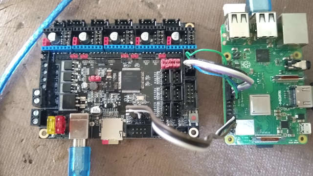
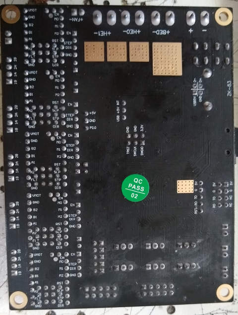
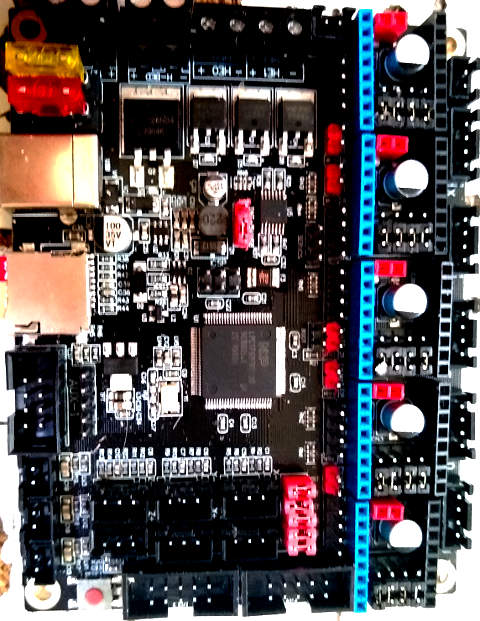
Since my board has no manufacturer marking, no code numbers, only the stock QC round label,
i cannot get manuals or schematics. Maybe i can trace from the cpu to the port pin
but thats unlikely given the steadiness of my hands. See attached photos.

"""you NEED a drawing of YOUR BOARD"""
that wont happen unles I draw it. The board, purchased in Thailand, from unknown Chinese supplier,
has no papers, it's an undocumented item. The seller does not recall where he got it. See ''inscrutable oriental"

"""Guessing is not good engineering or troubleshooting practice so do as little guessing as possible. """
Sometime a guess is all you got ;-)
I can try to ohm out from LPC1768 to jacks/sockets.
I did not know those pins directly connected to sockets, that sounds like a dangerous design, but I will try.
I have to see the schematics from the githubs to begin the trace at the cpu.

"""What? you have not installed stepper drivers?"""
No, its not a good idea to hook up hardware in this case. And an open loop stepper system should not care.
And not care if 3 axis versus 5.

"""SPI signals are high speed and they really belong in a transmission line cable and not just loose wires. The ideal SPI cable will have every other wire in a ribbon cable grounded and the signal wires carried in the other wires. So a 10 wire ribbon cable and even that cable needs to be ~200mm long at best and probably 120-140mm better.
"""
see photo, about 60mm long, not interleaved with grounds (yet, may do that but pin tracing comes first )
dang i wish i had a setup with pogo pins.

btw: i ordered a BTT SKR V1.4 Turbo 2 days ago, should come soon, seller was here in Thailand.
AFAICT its the real thing. ( see "inscrutable oriental" )
Thats not slander, its just the real uncertainty of answers to what see to be simple questions.
Q "Is this a real Big Tree Tech SKR V1.4 turbo?"
A: " Yes we have very good product"
aaarrrgh!

Thanks tomp
update:
i wrung out all the pins used for SPI. They are correct.
I used the top and bottom pdfs to verify layout of all componenets
then used the schematic and sewing needles to wring out
P1.32 MOSI0 MISO0 SSEL) SCK0 GND

so it is wired like the remora docs.
I used
raw.githubusercontent.com/bigtreetech/BI...are/SKR-V1.3-SCH.pdf

thanks again tomp

update2
i've gone into remora.c and enabled some debug prints ( author commented them out)
This showed that the SPI packet was 64 bytes of 255
Which is why the message 'bad SPI payload ffffffff' (ffffffff = 255 255 255 255)

The 1st 4 bytes of any SPI pkt has a man readable header.

'read' and 'writ' are token/prefixes for packets sent TO PRU.
'data' and 'estp' are prefixes for any packet received FROM PRU.
Any other header in the packet received is bad.

I verified that I send 'read' but always get back ffffffff ( 255 255 255 255 )

I scratched my head a lot trying to see why I was sending the PRU 100 97 101 114,
then it dawned on me that this was a little command/reply protocol.

I am no close to knowing why this LPC1768FDB100 is not cooperating.

tomp
Last edit: 5 years 4 months ago by tjtr33. Reason: update

Please Log in or Create an account to join the conversation.
More
5 years 4 months ago #212373 by scotta
Hi, the board looks like a v1.3 and the output from the remora boot up looks fine. Getting a bad payload points to a wiring issue. Can you post a close up photo of your ribbon cable connection?
The following user(s) said Thank You: tjtr33

Please Log in or Create an account to join the conversation.
More
5 years 4 months ago #212386 by Doogie
good stuff @tjtr33, sounds like it is ready to work if you can get the noise off the SPI connection. Since you are not using a ribbon cable but are using discrete wires, try moving them away from each other. ie spread them out bit so there's little chance of cross-talk across wires.

@scotta he posted 3 pics of the board and in the first one it also shows the rPi and the SPI connections.
The following user(s) said Thank You: tjtr33

Please Log in or Create an account to join the conversation.

Time to create page: 0.487 seconds
Powered by Kunena Forum