Understanding G64 behavior
- funkenjaeger
- Offline
- Junior Member
-

Less
More
- Posts: 23
- Thank you received: 2
25 Oct 2021 12:44 #224255
by funkenjaeger
Understanding G64 behavior was created by funkenjaeger
I'm using the generic LinuxCNC postprocessor provided in Fusion 360 and encountered some corners getting rounded pretty severely - but inconsistently:
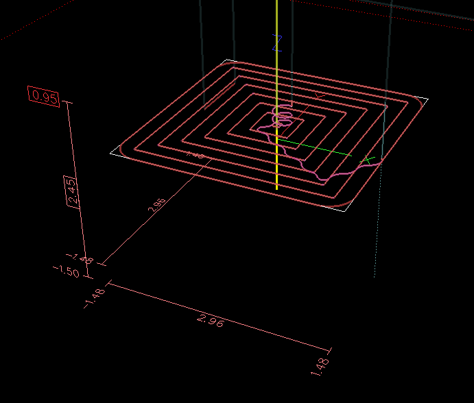
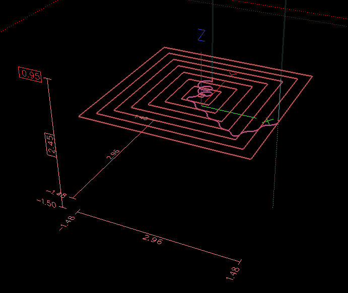
White being the path in the g-code, red the as-run path the machine took. Some quick searching revealed that apparently G64 (path blending) with no tolerance is the default, which would allow it to round the corners like that. Sure enough, I added ato the preamble (leaving the g-code otherwise unchanged) and it no longer rounded the corners:
Seems surprising that the default setting would allow such egregious deviations from the programmed toolpath, but at least there's an explanation - I guess I just need to edit a G64 P<> into the postprocessor going forward.
It still bothers me though that I don't completely understand the behavior I was seeing with the default setting - why did it only round off the corners on the outermost loop of this pocket operation, while it did pretty square corners for all the inner loops? In the subsequent operation (not included in this example g-code) I did a simple 2D contour to finish the inside of the pocket using a smaller diameter tool, and THAT operation followed the path closely, without rounding the corners, even with the default G64 setting
I'm running at about 0.25G acceleration (100 in/s^2) on my machine, and both operations were at similar feeds (~150-180 ipm) so I don't think this was a case of being acceleration-limited - the machine is easily hitting the full programmed feed rate on each of the straight-line segments.
Looking closer at the G-code, the one apparent difference between the inner loops and the outer one is that all the inner ones have straight-line G1 segments with very short G3 arcs in the corners, whereas the outer loop is exclusively G1 moves (i.e. perfectly sharp corners). So, a plausible explanation might be that G64 with no tolerance will happily round off sharp corners at the intersection of straight-line moves, but when there's even a microscopic little arc in the corner it follows the corner very closely(?)
Any insight appreciated - just looking to make sure I understand what's really happening before blindly adding a "fix".
White being the path in the g-code, red the as-run path the machine took. Some quick searching revealed that apparently G64 (path blending) with no tolerance is the default, which would allow it to round the corners like that. Sure enough, I added a
G64 P0.001
Seems surprising that the default setting would allow such egregious deviations from the programmed toolpath, but at least there's an explanation - I guess I just need to edit a G64 P<> into the postprocessor going forward.
It still bothers me though that I don't completely understand the behavior I was seeing with the default setting - why did it only round off the corners on the outermost loop of this pocket operation, while it did pretty square corners for all the inner loops? In the subsequent operation (not included in this example g-code) I did a simple 2D contour to finish the inside of the pocket using a smaller diameter tool, and THAT operation followed the path closely, without rounding the corners, even with the default G64 setting
I'm running at about 0.25G acceleration (100 in/s^2) on my machine, and both operations were at similar feeds (~150-180 ipm) so I don't think this was a case of being acceleration-limited - the machine is easily hitting the full programmed feed rate on each of the straight-line segments.
Looking closer at the G-code, the one apparent difference between the inner loops and the outer one is that all the inner ones have straight-line G1 segments with very short G3 arcs in the corners, whereas the outer loop is exclusively G1 moves (i.e. perfectly sharp corners). So, a plausible explanation might be that G64 with no tolerance will happily round off sharp corners at the intersection of straight-line moves, but when there's even a microscopic little arc in the corner it follows the corner very closely(?)
Any insight appreciated - just looking to make sure I understand what's really happening before blindly adding a "fix".
Please Log in or Create an account to join the conversation.
- bevins
-
- Offline
- Platinum Member
-

Less
More
- Posts: 1947
- Thank you received: 338
25 Oct 2021 13:47 - 25 Oct 2021 13:51 #224263
by bevins
Replied by bevins on topic Understanding G64 behavior
When you program a corner in G Code, the trajectory planner can do several things, all of which are right in some cases: it can decelerate to a stop exactly at the coordinates of the corner, and then accelerate in the new direction. It can also do what is called blending, which is to keep the feed rate up while going through the corner, making it necessary to round the corner off in order to obey machine constraints. You can see that there is a trade off here: you can slow down to get better path following, or keep the speed up and have worse path following. Depending on the particular cut, the material, the tooling, etc., the programmer may want to compromise differently.Rapid moves also obey the current trajectory control. With moves long enough to reach maximum velocity on a machine with low acceleration and no path tolerance specified, you can get a fairly round corner.
I most always use G64 P.001 , but this will cause to slow down at corners so it will stay within .001 of the path.
ref.1.2 Trajectory Control
I most always use G64 P.001 , but this will cause to slow down at corners so it will stay within .001 of the path.
ref.1.2 Trajectory Control
Last edit: 25 Oct 2021 13:51 by bevins.
Please Log in or Create an account to join the conversation.
- funkenjaeger
- Offline
- Junior Member
-
Less
More
- Posts: 23
- Thank you received: 2
25 Oct 2021 23:58 #224310
by funkenjaeger
Replied by funkenjaeger on topic Understanding G64 behavior
Makes sense, but the main thing that surprised me is how a sharp corner is treated completely different than a corner with an extremely small arc joining the two straight segments (looks like 0.0128" radius in this case) even though to the naked eye those are very close to the same path - it behaves almost as if it's in exact-stop mode for the corners with arcs, even as it dramatically rounds off the square corners.
It's as though the trajectory planner is only looking one move ahead, because it seems like if it were looking further ahead then it should treat the two types of corners more or less the same. Just curious how it works under the hood.
It's as though the trajectory planner is only looking one move ahead, because it seems like if it were looking further ahead then it should treat the two types of corners more or less the same. Just curious how it works under the hood.
Please Log in or Create an account to join the conversation.
- andypugh
-

- Offline
- Moderator
-

Less
More
- Posts: 19879
- Thank you received: 4643
04 Nov 2021 01:10 #225180
by andypugh
Replied by andypugh on topic Understanding G64 behavior
I think (might be wrong) that the planner is obliged to at least _touch_ each segment. So if there is a small arc then it will slow down enough to touch it.
The main driver for all this is the joint acceleration limits. You only really see these gross deviations when the speed is high relative to the acceleration. Did you guess your accel limits, or are they based on what the machine is capable of?
The main driver for all this is the joint acceleration limits. You only really see these gross deviations when the speed is high relative to the acceleration. Did you guess your accel limits, or are they based on what the machine is capable of?
Please Log in or Create an account to join the conversation.
- funkenjaeger
- Offline
- Junior Member
-
Less
More
- Posts: 23
- Thank you received: 2
04 Nov 2021 02:19 #225188
by funkenjaeger
Replied by funkenjaeger on topic Understanding G64 behavior
I'm running clearpath servos so I know they're faithfully obeying the commanded motion with no more than a trivial amount of positional error at any point; I've also tested them in-situ to 1G (386 in/s^2) before, so I know that the current acceleration limits are just a fraction of what the machine can handle. My back-of-the envelope math says 100 in/s^2 should be able to pull a much tighter corner than the >0.25" radius it did, but the magnitude of the radius isn't really my concern.
If the planner is in fact obliged to touch each segment as you suspect, then that would seem to explain what I saw.
If the planner is in fact obliged to touch each segment as you suspect, then that would seem to explain what I saw.
Please Log in or Create an account to join the conversation.
- Michael
- Offline
- Platinum Member
-
Less
More
- Posts: 335
- Thank you received: 59
04 Nov 2021 05:13 #225199
by Michael
Replied by Michael on topic Understanding G64 behavior
What type of system are the clear paths running on? I have servos that can't run half that acceleration on linear rails and perfect ballscrews. The napkin is very different then what they deliver once you introduce inertia to them. Just because they are closed loop in their driver doesn't mean they are keeping up with the commanded speeds from Linux CNC. If I remember they only report when they don't complete steps, not if they are keeping up.
Could be way wrong
Could be way wrong
Please Log in or Create an account to join the conversation.
- rodw
-

- Offline
- Platinum Member
-
Less
More
- Posts: 12041
- Thank you received: 4109
04 Nov 2021 06:08 #225202
by rodw
Replied by rodw on topic Understanding G64 behavior
If you think about it, its not possible to produce a square internal corner with a round tool but you can on an outside cut. I think this likely expalins the different behaviour.
There is actually some interesting reading about the trajectory planner and how different settings change behaviour in the docs, but I'm sure none of us bother to read it!
There is actually some interesting reading about the trajectory planner and how different settings change behaviour in the docs, but I'm sure none of us bother to read it!
Please Log in or Create an account to join the conversation.
- andypugh
-
- Offline
- Moderator
-
Less
More
- Posts: 19879
- Thank you received: 4643
04 Nov 2021 09:40 #225216
by andypugh
linuxcnc.org/docs/2.8/html/user/user-con...#_trajectory_control
Replied by andypugh on topic Understanding G64 behavior
It depends on the settings, but is mentioned here:If the planner is in fact obliged to touch each segment as you suspect, then that would seem to explain what I saw.
linuxcnc.org/docs/2.8/html/user/user-con...#_trajectory_control
Please Log in or Create an account to join the conversation.
- funkenjaeger
- Offline
- Junior Member
-
Less
More
- Posts: 23
- Thank you received: 2
04 Nov 2021 16:46 #225242
by funkenjaeger
Replied by funkenjaeger on topic Understanding G64 behavior
I'm running rack & pinion drives on X and Y axes, so the final drive ratio is lower than you'd have with ballscrews - good for speed, makes the motor work that much harder to accelerate. The machine is a router, very similar in construction to the Avid pro series - I'd guesstimate the moving mass at about 150lb, so it's not nearly as massive as a cast iron mill. The clearpath servos allow you to plug in a USB cable and monitor all sorts of internal signals, including actual position error vs. commanded, with resolution down to the individual encoder count level - captured oscilloscope-style during actual movement. In my early testing where I experimented with higher accelerations I used that extensively. The position error during aggressive moves (e.g. point-to-point move of several inches, long enough to easily reach maxvel of 1250ipm, with 250 in/s^2 accel) showed clearly a slightly underdamped response, indicating that it was not suffering from insufficient acceleration (in which case I would expect a very overdamped response). Also, the peak values of position error even during such a move were on the order of tens of encoder counts; on my machine, between the servo encoder resolution and my drive ratio that works out to on the order of ones to tens of thousandths of an inch. Now that I'm actually running a much lower acceleration operationally it's even better.What type of system are the clear paths running on? I have servos that can't run half that acceleration on linear rails and perfect ballscrews. The napkin is very different then what they deliver once you introduce inertia to them. Just because they are closed loop in their driver doesn't mean they are keeping up with the commanded speeds from Linux CNC. If I remember they only report when they don't complete steps, not if they are keeping up.
Please Log in or Create an account to join the conversation.
- funkenjaeger
- Offline
- Junior Member
-
Less
More
- Posts: 23
- Thank you received: 2
04 Nov 2021 16:47 #225243
by funkenjaeger
Replied by funkenjaeger on topic Understanding G64 behavior
Your first point is true, however - this toolpath is cutting a pocket from the inside out, so every corner it cuts there is an inside corner. The tightest internal radius a round end mill can produce is the radius of the tool itself, where the tool follows a path with a perfectly sharp corner (e.g. a perfect right angle in this case). The cut radius I ended up with in the outermost pass of the example above (before defining a tolerance) was on the order of 0.5", about 4 times the radius of the tool. And LinuxCNC doesn't "know" whether it's cutting an inside or outside corner, that distinction would need to come from CAM - which it didn't.If you think about it, its not possible to produce a square internal corner with a round tool but you can on an outside cut. I think this likely expalins the different behaviour.
Please Log in or Create an account to join the conversation.
Time to create page: 0.316 seconds