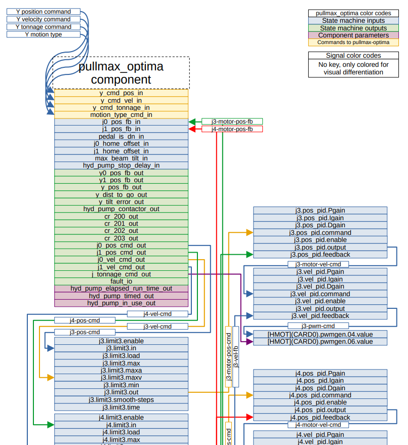
Don't know whether this would be a solution for your use case or not, I have been doing this in libreoffice draw. Sometimes I get to crowding the pages a bit, but if I'm not planning on printing to paper it is easy enough to set the page size larger.
Each hal component pin is an individual rectangle. The signal wires are 'connectors' so they readily stick to the rectangles and come with when I pull rectangles around. For the signal names I've just been pasting smaller rectangles on top of the connector lines. They're not attached and easily get lost if I start rearranging stuff. Next time I'm drawing one of these I want to use two connector lines to one signal like:
[hal pin a] - - - [signal name] - - - >[hal pin b]
(still in libreoffice draw) the first connector will be drawn from "hal pin a" to the signal name rectangle. The second one will be from signal name to "hal pin b"
With the rectangles I do a lot of copy/paste. I don't drag them around much with the mouse, rather select and move in increments with the arrow keys or enter calculated positions.
I frequently work with the page display zoomed in some when doing this, makes it easier to grab the handles.
I see andypugh has his input/output pins left vs right justified, that is a new idea for me, I'll start doing that way as well. I had all my text center justified.