Spindle orient PID tuning [re-solved, yay]
- spumco
- Offline
- Platinum Member
-

Less
More
- Posts: 2043
- Thank you received: 838
13 Jun 2022 01:11 #245046
by spumco
I tried a limit2 just wildly guessing at values, and the result was the spindle rotating continuously in one direction.
limit2.0.min 0
limit2.0.max 50
limit2.0.maxv 50
Obiously the MAN page doesn't provide any context or indicate what the units are, nor do any of the (few) examples I could dig up in the forum. I'll go with the RPS & RPS/S you indicate.
Do I need a negative number for limit3.0.min?
Replied by spumco on topic Spindle orient PID tuning? [So close but no dice]
Actually limit3 is needed
Starting values for the bounds should be pretty easy to set
maxv is in RPS and maxa is in RPS/S
I tried a limit2 just wildly guessing at values, and the result was the spindle rotating continuously in one direction.
limit2.0.min 0
limit2.0.max 50
limit2.0.maxv 50
Obiously the MAN page doesn't provide any context or indicate what the units are, nor do any of the (few) examples I could dig up in the forum. I'll go with the RPS & RPS/S you indicate.
Do I need a negative number for limit3.0.min?
Please Log in or Create an account to join the conversation.
- spumco
- Offline
- Platinum Member
-
Less
More
- Posts: 2043
- Thank you received: 838
13 Jun 2022 02:36 #245048
by spumco
Replied by spumco on topic Spindle orient PID tuning? [So close but no dice]
Right now I'm just running the little orient program over and over, fiddling with input values to see what happens. Not really making progress, TBH.
Can anyone tell me why the orient pid output is jumping up and down in steps? It's not outputtting a steadily increasing or decreasing value - just a series of spikes with different amplitudes?
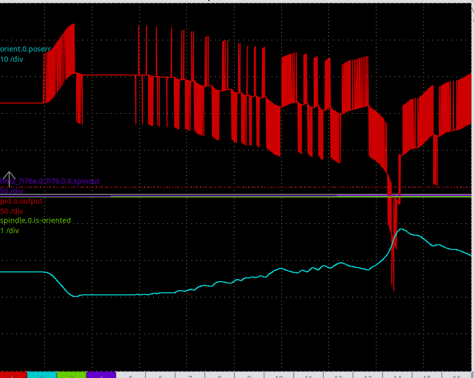
Can anyone tell me why the orient pid output is jumping up and down in steps? It's not outputtting a steadily increasing or decreasing value - just a series of spikes with different amplitudes?
Attachments:
Please Log in or Create an account to join the conversation.
- PCW
-

- Offline
- Moderator
-

Less
More
- Posts: 17843
- Thank you received: 5221
13 Jun 2022 02:59 #245049
by PCW
Replied by PCW on topic Spindle orient PID tuning? [So close but no dice]
My guess is that the spikes are because you have a high D term and you are not using
the PIDs derivative input so every encoder count generate a large (dC/dT) spike
Can you plot the commanded and actual position?
the PIDs derivative input so every encoder count generate a large (dC/dT) spike
Can you plot the commanded and actual position?
Please Log in or Create an account to join the conversation.
- spumco
- Offline
- Platinum Member
-
Less
More
- Posts: 2043
- Thank you received: 838
13 Jun 2022 03:48 - 13 Jun 2022 03:50 #245050
by spumco
Replied by spumco on topic Spindle orient PID tuning? [So close but no dice]
Not sure which pins are useful for you to review position vs commanded. I tried orient.0.position and orient.0.command, but they are just flat-lined in halscope.
EDIT
This is with lincurve re-enabled and the limit3 turned off. Let me know which pins to set for channels 3 & 4 and I'll run it again.
EDIT
This is with lincurve re-enabled and the limit3 turned off. Let me know which pins to set for channels 3 & 4 and I'll run it again.
Attachments:
Last edit: 13 Jun 2022 03:50 by spumco.
Please Log in or Create an account to join the conversation.
- andypugh
-

- Offline
- Moderator
-
Less
More
- Posts: 19848
- Thank you received: 4630
15 Jun 2022 11:09 #245182
by andypugh
Replied by andypugh on topic Spindle orient PID tuning? [So close but no dice]
I think that we need to see the pid.o.feedback pin to understand what is going on.
The following user(s) said Thank You: spumco
Please Log in or Create an account to join the conversation.
- spumco
- Offline
- Platinum Member
-
Less
More
- Posts: 2043
- Thank you received: 838
15 Jun 2022 11:34 #245185
by spumco
Replied by spumco on topic Spindle orient PID tuning? [So close but no dice]
Will do, soon as I get home tonight.
I'm also working on a secret project that should help nail the final position with 100% reliability.
I'm also working on a secret project that should help nail the final position with 100% reliability.
Please Log in or Create an account to join the conversation.
- spumco
- Offline
- Platinum Member
-
Less
More
- Posts: 2043
- Thank you received: 838
17 Jun 2022 20:17 #245348
by spumco
Replied by spumco on topic Spindle orient PID tuning? [So close but no dice]
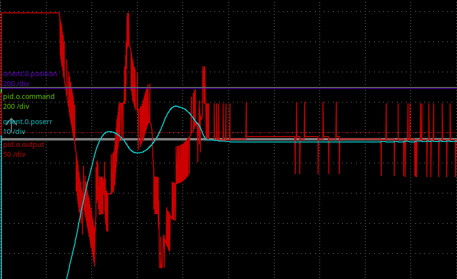
Two halscope screen shots attached with pid.o.feedback included. First one failed to orient in time, second one nailed it quickly.
pid.0.feedback doesn't seem to be doing a whole lot - it's basically the same thing as orient.0.position and doesn't reset to "0" between orient commands so there's no way to trend anything.
Unless I've got my HAL connections horribly wrong?
And another thing...
I just noticed it's not going to the same orient location each time I start up the machine. I spent quite some time fiddling with the INI orient_offset a couple days ago to get it perfectly lined up with the carousel pockets, and the 'completed' orient cycle today (attached) wound up about 60 degrees off from the last time I had the machine running.
Please Log in or Create an account to join the conversation.
- tommylight
-

- Away
- Moderator
-
Less
More
- Posts: 21497
- Thank you received: 7327
18 Jun 2022 00:01 #245361
by tommylight
Replied by tommylight on topic Spindle orient PID tuning? [So close but no dice]
That is a loooooong hal file ! ")
Just an advice to make your life easier, add the Orient section with their respective values to the INI file and add references to them from the HAL file, that way you can open "calibration" from the "machine" menu in LinuxCNC and do tuning without the need to restart LinuxCNC after every value change.
Just an advice to make your life easier, add the Orient section with their respective values to the INI file and add references to them from the HAL file, that way you can open "calibration" from the "machine" menu in LinuxCNC and do tuning without the need to restart LinuxCNC after every value change.
Please Log in or Create an account to join the conversation.
- spumco
- Offline
- Platinum Member
-
Less
More
- Posts: 2043
- Thank you received: 838
18 Jun 2022 02:43 #245372
by spumco
Replied by spumco on topic Spindle orient PID tuning? [So close but no dice]
Thanks Tommy. All that stuff is in HAL for the moment because it's easy to tune it right from halshow.
Once everything is sorted out I'll move them to INI and probably create a number of hal files for the various i/o, spindle, ATC, etc.
Once everything is sorted out I'll move them to INI and probably create a number of hal files for the various i/o, spindle, ATC, etc.
The following user(s) said Thank You: tommylight
Please Log in or Create an account to join the conversation.
- spumco
- Offline
- Platinum Member
-
Less
More
- Posts: 2043
- Thank you received: 838
19 Jun 2022 04:07 #245420
by spumco
Replied by spumco on topic Spindle orient PID tuning [Brute Force Solution!]
For those of you still following along patiently, I got tired of trying to get the spindle to orient and failing. Maybe with more tuning it'd be OK, but I really need it to be 100% reliable. Even 99% reliable means 1 out of 100 tool changes will fail - not acceptable.
I think the biggest probelm is that I've got a 2-pole induction motor spindle, and the VFD just isn't capable of really fine, low-speed positioning type moves. The VFD is great at low RPM, but it's fighting the motor and spindle inertia.
And I'm sure Andy (and others) are sick of holding my hand through this one even if they haven't bit my head off yet.

So... I concluded a mechanical solution was in order. LCNC gets it close, and a shot-pin of some sort nails the position.
Step 1 - find an air cylinder. (happened to have a couple of cute little Festos in the junk drawer)
Step 2 - mount something on the spindle with a notch for the air cylinder to engage
Step 3 - mount something on the end of the air cylinder to engage the notch
Step 4 - fire the air cylinder and then run the orient cycle
Step 5 - spindle orients, gets close, and the air cylinder forces whatever it is in to the notch and locks it in the right place.
Taking a page from the old Fadal orientation lock assembly, I turned a brass ring that fits over the spindle upper preload nut. This nut has 3 spanner pockets just right for set screws to lock in. Drill 3 holes for set screws, mount it on the nut with a slight press fit, and snug it down.
Mount some 11mm OD roller bearings to the end of an air cylinder. These roll on the brass ring while it's doing the orient move.
Slide the ATC carousel in and engage a pocket on a tool in the spindle. Rotate the tool in the fork a bit (my forks have BT30 alignment tangs), and mark where the air cylinder lock rollers just touch the ring.
Get the ring off, and use a 3/8" end mill to plunge straight down through the ring. I made the arc pocket about 0.100" deep (radius), so a little less than 1/4 of the bearings drop in to the pocket. And because the pocket is slightly narrower than the bearing, the bearing is only touching at two contact lines - no rocking back and forth in a valley. Plus the pocket can wear a bit over time and still have precise alignment.
Connect the air cylinder to a solenoid valve with some speed valves so it doesn't slam.
Connect the valve to a spare Mesa output, and then to motion.digital-out-nn. Solenoid valve is a 3-way, so the rest position is retracted.
Extending the rollers and letting them ride on the brass ring seems to work just fine - LCNC moves the spindle at M19, and it just has to get within about +/- 10 degrees and the air pressure on the bearings forces the pocket (and thus the spindle) in to alignment. LCNC sees that it's within the alignment tolerance and shuts off - no fighting the alignment lock.
Just tested it and it nailed the orient in half a second 10 out of 10 times. No fighting, no drama, no noise - bang on.
Next step is to wire up the proximity sensor that came with the cylinder and connect it to motion.digital-in-nn for a safety function. I don't want the spindle to start with this thing engaged. On the other hand, I think the roller & shallow pocket will cause way less damage than a traditional tapered pin & notch if something goes sideways.
And I've got a spare air cylinder if I do damage something...

There's probably a more elegant way to do this, like using a spring-loaded bellcrank so the air cylinder rod isn't seeing any side loads. But this seems to work and now I can get back to the main ATC project.
I think the biggest probelm is that I've got a 2-pole induction motor spindle, and the VFD just isn't capable of really fine, low-speed positioning type moves. The VFD is great at low RPM, but it's fighting the motor and spindle inertia.
And I'm sure Andy (and others) are sick of holding my hand through this one even if they haven't bit my head off yet.
So... I concluded a mechanical solution was in order. LCNC gets it close, and a shot-pin of some sort nails the position.
Step 1 - find an air cylinder. (happened to have a couple of cute little Festos in the junk drawer)
Step 2 - mount something on the spindle with a notch for the air cylinder to engage
Step 3 - mount something on the end of the air cylinder to engage the notch
Step 4 - fire the air cylinder and then run the orient cycle
Step 5 - spindle orients, gets close, and the air cylinder forces whatever it is in to the notch and locks it in the right place.
Taking a page from the old Fadal orientation lock assembly, I turned a brass ring that fits over the spindle upper preload nut. This nut has 3 spanner pockets just right for set screws to lock in. Drill 3 holes for set screws, mount it on the nut with a slight press fit, and snug it down.
Mount some 11mm OD roller bearings to the end of an air cylinder. These roll on the brass ring while it's doing the orient move.
Slide the ATC carousel in and engage a pocket on a tool in the spindle. Rotate the tool in the fork a bit (my forks have BT30 alignment tangs), and mark where the air cylinder lock rollers just touch the ring.
Get the ring off, and use a 3/8" end mill to plunge straight down through the ring. I made the arc pocket about 0.100" deep (radius), so a little less than 1/4 of the bearings drop in to the pocket. And because the pocket is slightly narrower than the bearing, the bearing is only touching at two contact lines - no rocking back and forth in a valley. Plus the pocket can wear a bit over time and still have precise alignment.
Connect the air cylinder to a solenoid valve with some speed valves so it doesn't slam.
Connect the valve to a spare Mesa output, and then to motion.digital-out-nn. Solenoid valve is a 3-way, so the rest position is retracted.
Extending the rollers and letting them ride on the brass ring seems to work just fine - LCNC moves the spindle at M19, and it just has to get within about +/- 10 degrees and the air pressure on the bearings forces the pocket (and thus the spindle) in to alignment. LCNC sees that it's within the alignment tolerance and shuts off - no fighting the alignment lock.
Just tested it and it nailed the orient in half a second 10 out of 10 times. No fighting, no drama, no noise - bang on.
Next step is to wire up the proximity sensor that came with the cylinder and connect it to motion.digital-in-nn for a safety function. I don't want the spindle to start with this thing engaged. On the other hand, I think the roller & shallow pocket will cause way less damage than a traditional tapered pin & notch if something goes sideways.
And I've got a spare air cylinder if I do damage something...
There's probably a more elegant way to do this, like using a spring-loaded bellcrank so the air cylinder rod isn't seeing any side loads. But this seems to work and now I can get back to the main ATC project.
The following user(s) said Thank You: tommylight, Clive S, mgm
Please Log in or Create an account to join the conversation.
Time to create page: 1.314 seconds