- Hardware & Machines
- Driver Boards
- Trouble Shooting Universal Stepper Controller with Gecko Interface
Trouble Shooting Universal Stepper Controller with Gecko Interface
- 3DTOPO
-
 Topic Author
- Offline
- Senior Member
-

- Posts: 47
- Thank you received: 3
I've traced the wires, and everything so far seems to check out. If I manually move the encoder, the value will only go one way. Eg it will only get larger, but if I swap the encoder A and B signals, it will only get smaller. The encoder checks out on one of the functional axes. I guess that may indicate that only one of the channels is being seen by the board or Gecko?
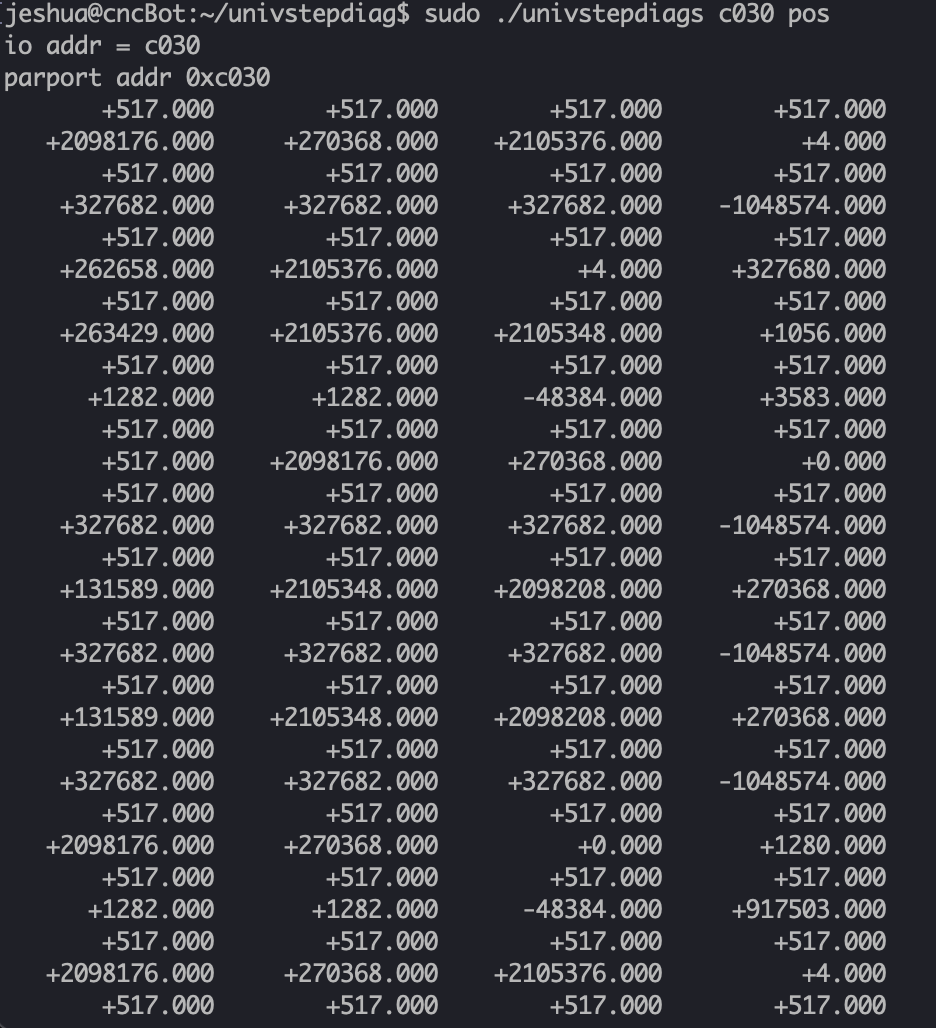
If I run univstepdiag pos, all the axes largely look the same to me. I'm not sure what I am looking for.
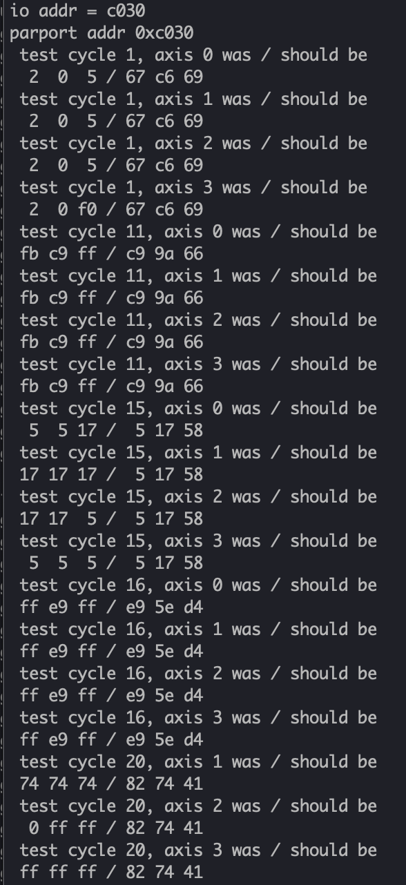
Here is the output from commtest, again not sure if this looks right or not.
Are there any other tests I can run? Any connections that I should verify?
I think there is a way to check the encoder signals with a voltmeter, but I don't recall the specifics.
I really appreciate any and all advice.
Attachments:
Please Log in or Create an account to join the conversation.
- jmelson
- Offline
- Moderator
-

- Posts: 520
- Thank you received: 126
First, when you power the USC on, make sure the "load fail" red LED flashes for a fraction of a second and then goes out. Then, make sure the parallel port is set for EPP mode. It may be necessary to run the pcisetup program to set the port to EPP mode, but that is slightly complicated with PCI plugin cards at different addresses.
I think the address you should specify in pcisetup for the c030 parport is bc30 (or maybe bc2e). This is only needed for the diagnostic, LinuxCNC already knows how to set the port for EPP mode.
Jon
Please Log in or Create an account to join the conversation.
- 3DTOPO
-
Topic Author
- Offline
- Senior Member
-
- Posts: 47
- Thank you received: 3
In the past, if the parallel port wasn't in EPP mode, I couldn't even get the diagnostics to see the card. But I tried both:
sudo pcisetup bc30
sudo pcisetup bc2e
And it looks like commtest is failing miserably still:
sudo ./univstepdiags c030 commtest:
...
test cycle 999, axis 1 was / should be
ff ff ff / 1 96 17
test cycle 999, axis 2 was / should be
ff ff ff / 1 96 17
test cycle 999, axis 3 was / should be
ff ff ff / 1 96 17
1000 test cycles, 3996 errors
In the past, it looks like I've used 'showport' which I also tried:
jeshua@cncBot:~/univstepdiag$ sudo ~/showport C030 C040 e
~~~~~
Base @ 0xc030
Extended @ 0xc040
DPR: 4
DSR: 232
DCR: 4
EPPA: 4
EPPD: 4
CFA: 255
CFB: 255
ECR: 255
~~~~~
Setting mode to EPP
ECR: 255
~~~~~
Here is the par port from /proc/ioports:
0d00-ffff : PCI Bus 0000:00
c000-cfff : PCI Bus 0000:07
c000-cfff : PCI Bus 0000:08
c000-c007 : 0000:08:01.2
c010-c017 : 0000:08:01.2
c010-c012 : parport1
c013-c017 : parport1
c020-c027 : 0000:08:01.0
c030-c037 : 0000:08:01.0
c030-c032 : parport0
c033-c037 : parport0
c430-c432 : k
Please Log in or Create an account to join the conversation.
- 3DTOPO
-
Topic Author
- Offline
- Senior Member
-
- Posts: 47
- Thank you received: 3
io addr = c030
parport addr 0xc030
1000 test cycles, 0 errors
2000 test cycles, 0 errors
3000 test cycles, 0 errors
4000 test cycles, 0 errors
5000 test cycles, 0 errors
The pos printed messages makes sense now. But I can only get the X pos to go in one direction only (depending on encoder signals A/B switched).
jeshua@cncBot:~$ sudo univstepdiag/univstepdiags c030 pos
io addr = c030
parport addr 0xc030
+497.000 +517.000 +517.000 +517.000
Please Log in or Create an account to join the conversation.
- jmelson
- Offline
- Moderator
-
- Posts: 520
- Thank you received: 126
Are you sure C030 is the correct port address that was used before? If you change configuration of what is in any PCI slots it COULD change the address of the parport board.Setting mode to EPP
ECR: 255
Well, it looks like this is setting it to EPP mode, too.
Please Log in or Create an account to join the conversation.
- 3DTOPO
-
Topic Author
- Offline
- Senior Member
-
- Posts: 47
- Thank you received: 3
Please Log in or Create an account to join the conversation.
- jmelson
- Offline
- Moderator
-
- Posts: 520
- Thank you received: 126
OH, of course! You cannot have two programs commanding the board at the same time.My bad! I quit out of Axis and it works as expected:
So, is there still a problem with the X encoder?
Jon
Please Log in or Create an account to join the conversation.
- 3DTOPO
-
Topic Author
- Offline
- Senior Member
-
- Posts: 47
- Thank you received: 3
I'm not using the 4th axis. Does it make any sense to try the 4th axis of the Gecko Interface? It's not easy for me to change to USC because all the connections are soldered to the board but it is easy to change the plug on the Gecko Interface.
Please Log in or Create an account to join the conversation.
- jmelson
- Offline
- Moderator
-
- Posts: 520
- Thank you received: 126
Yes, try the 4th channel of the gecko interface. That will use a different input on the USC board. It is also possible that the encoder has some defect. Does the Gecko servo drive respond properly to movement of the encoder? IE. gives restoring torque in both directions? That would indicate the encoder is good, and good signals are being transmitted to the Gecko drive. You will also have to move the encoder to different pins on J5 of the Gecko interface.Correct. The X encoder will increment in one direction only when I manually spin it.
I'm not using the 4th axis. Does it make any sense to try the 4th axis of the Gecko Interface? It's not easy for me to change to USC because all the connections are soldered to the board but it is easy to change the plug on the Gecko Interface.
Why did you solder wires to the USC?
Jon
Please Log in or Create an account to join the conversation.
- 3DTOPO
-
Topic Author
- Offline
- Senior Member
-
- Posts: 47
- Thank you received: 3
OK, will do, thanks.jmelson post=240368 userid=508
Yes, try the 4th channel of the gecko interface
I tested the encoder on a functional axes and it works as expected.It is also possible that the encoder has some defect.
Hmm, actually I don't know. My routine is to first check encoders before connection the power. But I'll disconnect the belt from the servo pulley and try.Does the Gecko servo drive respond properly to movement of the encoder? IE. gives restoring torque in both directions? That would indicate the encoder is good, and good signals are being transmitted to the Gecko drive.
OK thanks. I guess I was hoping I could just change things in the configuration without having to mess with the USC. But I got to do what I got to do!That will use a different input on the USC board.
You will also have to move the encoder to different pins on J5 of the Gecko interface.
No matter what wire I tried and techniques using the push slots, I always had trouble with wires falling out or not having solid connections.Why did you solder wires to the USC?
Please Log in or Create an account to join the conversation.
- Hardware & Machines
- Driver Boards
- Trouble Shooting Universal Stepper Controller with Gecko Interface