

- Posts: 544
- Thank you received: 106
Request G6, Ellipse and G7, bezier curve
6 years 4 months ago #170956
by bbsr_5a
Replied by bbsr_5a on topic Request G6, Ellipse and G7, bezier curve
most cam will split this bezier in 2-3 regulair radius ones
never have had any problem on this on freecad or sheetcam with imported DXF
freecad draft can also make you regular rad out of bezier
never have had any problem on this on freecad or sheetcam with imported DXF
freecad draft can also make you regular rad out of bezier
The following user(s) said Thank You: Grotius
Please Log in or Create an account to join the conversation.

6 years 4 months ago #170958
by Aciera
Replied by Aciera on topic Request G6, Ellipse and G7, bezier curve
Sounds interesting BUT
It seems to me that NURBS-interpolation has kind of fallen by the wayside in professional machine controllers due to the increase in processing speed and memory size.
What CAM can actually output the code required for NURBS interpolation on the controller?
It seems to me that NURBS-interpolation has kind of fallen by the wayside in professional machine controllers due to the increase in processing speed and memory size.
What CAM can actually output the code required for NURBS interpolation on the controller?
The following user(s) said Thank You: Grotius
Please Log in or Create an account to join the conversation.
6 years 4 months ago #170961
by Grotius
Replied by Grotius on topic Request G6, Ellipse and G7, bezier curve
Hi Rod,
I also want to make some changes to the core code. Maybe we can work together...
Is oke for me. Did you already find out how to make a external c connection to hal?
If not, let me know over here. What change do you want to make?
I think the new G code will need to align with an existing gcode flavour so that there is post processor support.
I agree. But for 99% of the cam program's it will not work at this moment.
They have to improve their source code first.
For my CadCam program this new Gcode is working right away, this is how i would like to see a Cam program shitting out some gcode. High end gcode output. It opens more then only that. Pockets algoritmes, build up from splines. Wow.
@Aciera,
Sounds interesting BUT
It seems to me that NURBS-interpolation has kind of fallen by the wayside in professional machine controllers due to the increase in processing speed and memory size.
Nurbs are a kind of special. I never seen them around in dxf files. More common used one's are splines, ellipses and beziers.
I like the Nurbs idea and tested them yesterday in linuxcnc. A spline path instead of a nurb path can be considered as a good alternative.
What CAM can actually output the code required for NURBS interpolation on the controller?
That's the whole point. Now is the time to get Cam outputs in line with Cad data, and now is the time to get the EMC software up to date to do this job.
@bbsr,
most cam will split this bezier in 2-3 regulair radius ones
So far i know, sheetcam, dxf2gcode, pronest, etc will shit out thousands of line segments instead of one line of special G5 code.
And it is loosing path accuracy this way. For a cnc electron microscope, or a stealth fighter you can not interpolate this way.
never have had any problem on this on freecad or sheetcam with imported DXF
Actual, there is no real problem. There is a linuxcnc source code improvent request.
freecad draft can also make you regular rad out of bezier
But linuxcnc don't accepts this kind of shapes today. If linuxcnc has this option, you will see all cam program's will
improve their souce code.
I also want to make some changes to the core code. Maybe we can work together...
Is oke for me. Did you already find out how to make a external c connection to hal?
If not, let me know over here. What change do you want to make?
I think the new G code will need to align with an existing gcode flavour so that there is post processor support.
I agree. But for 99% of the cam program's it will not work at this moment.
They have to improve their source code first.
For my CadCam program this new Gcode is working right away, this is how i would like to see a Cam program shitting out some gcode. High end gcode output. It opens more then only that. Pockets algoritmes, build up from splines. Wow.
@Aciera,
Sounds interesting BUT
It seems to me that NURBS-interpolation has kind of fallen by the wayside in professional machine controllers due to the increase in processing speed and memory size.
Nurbs are a kind of special. I never seen them around in dxf files. More common used one's are splines, ellipses and beziers.
I like the Nurbs idea and tested them yesterday in linuxcnc. A spline path instead of a nurb path can be considered as a good alternative.
What CAM can actually output the code required for NURBS interpolation on the controller?
That's the whole point. Now is the time to get Cam outputs in line with Cad data, and now is the time to get the EMC software up to date to do this job.
@bbsr,
most cam will split this bezier in 2-3 regulair radius ones
So far i know, sheetcam, dxf2gcode, pronest, etc will shit out thousands of line segments instead of one line of special G5 code.
And it is loosing path accuracy this way. For a cnc electron microscope, or a stealth fighter you can not interpolate this way.
never have had any problem on this on freecad or sheetcam with imported DXF
Actual, there is no real problem. There is a linuxcnc source code improvent request.
freecad draft can also make you regular rad out of bezier
But linuxcnc don't accepts this kind of shapes today. If linuxcnc has this option, you will see all cam program's will
improve their souce code.
The following user(s) said Thank You: tommylight, rodw
Please Log in or Create an account to join the conversation.
6 years 4 months ago #170965
by Aciera
Replied by Aciera on topic Request G6, Ellipse and G7, bezier curve
I see you're an optimist! Good on ya!If linuxcnc has this option, you will see all cam program's will
improve their souce code.
The following user(s) said Thank You: tommylight, Grotius
Please Log in or Create an account to join the conversation.
6 years 4 months ago - 6 years 4 months ago #171153
by Grotius
Replied by Grotius on topic Request G6, Ellipse and G7, bezier curve
Hi,
Rodw wrote :
I think the new G code will need to align with an existing gcode flavour so that there is post processor support.
Check the next proposal, let me know how you think about it.
If you like it. I can dig into the source code of linuxcnc, and make a template in 5 minutes :laugh:
Gcode format proposal for natural cubic splines, bezier curves and ellipse.
Existing G formats:
G5 Cubic Spline
G5.1 Quadratic Spline
G5.2 G5.3 NURBS Block
To integrate:
G5.4 G5.5 Natural cubic spline (spline trough points, used in Inkscape and Freecad dxf outputs)
G5.6 G5.7 Bezier curve
G5.8 Ellipse cw
G5.9 Ellipse ccw
G5.10 Motion Interpolation Template MIT.
Why a G5.4 and a G5.5 block for one spline?
It's the same setup as Nurbs, we use a start-block and a end-block.
Example :
G0 X0 Y0 (start of the spline)
F1500
G5.4 (start block)
X10 Y10 (first control point)
X100 Y100 (second control point)
X250 Y25 (etc)
X350 Y-20
X600 Y0
G5.5 (end block)
The same format is for bezier curve :
G0 X0 Y0
F1500
G5.6 P1 L3 (start block)
X0 Y0
X0 Y100
X100 Y100
X100 Y0
G5.7 (end block)
(mention, if a 5fth point is attached to the bezier curve, we can expand the to a 4th degree bezier curve later on, you see i am
an optimist ).
Ellipse cw:
G0 X0 Y0
F1500
G5.8 X50 Y50 I20 J20 (clockwise cw)
Ellipse ccw:
G0 X0 Y0
F1500
G5.9 X50 Y50 I20 J20 (counter_clockwise ccw)
For ellipse i like to add the following letter packs into the gcode intepreter:
RA = ratio
PS = pi start angle
PE = pi end angle
I = center_x - start_x, J = center_y - start_y, in line with G2, G3, etc.
Added c++ functions for natural cubic spline, bezier curve and ellipse.
Rodw wrote :
I think the new G code will need to align with an existing gcode flavour so that there is post processor support.
Check the next proposal, let me know how you think about it.
If you like it. I can dig into the source code of linuxcnc, and make a template in 5 minutes :laugh:
Gcode format proposal for natural cubic splines, bezier curves and ellipse.
Existing G formats:
G5 Cubic Spline
G5.1 Quadratic Spline
G5.2 G5.3 NURBS Block
To integrate:
G5.4 G5.5 Natural cubic spline (spline trough points, used in Inkscape and Freecad dxf outputs)
G5.6 G5.7 Bezier curve
G5.8 Ellipse cw
G5.9 Ellipse ccw
G5.10 Motion Interpolation Template MIT.
Why a G5.4 and a G5.5 block for one spline?
It's the same setup as Nurbs, we use a start-block and a end-block.
Example :
G0 X0 Y0 (start of the spline)
F1500
G5.4 (start block)
X10 Y10 (first control point)
X100 Y100 (second control point)
X250 Y25 (etc)
X350 Y-20
X600 Y0
G5.5 (end block)
The same format is for bezier curve :
G0 X0 Y0
F1500
G5.6 P1 L3 (start block)
X0 Y0
X0 Y100
X100 Y100
X100 Y0
G5.7 (end block)
(mention, if a 5fth point is attached to the bezier curve, we can expand the to a 4th degree bezier curve later on, you see i am
an optimist
).Ellipse cw:
G0 X0 Y0
F1500
G5.8 X50 Y50 I20 J20 (clockwise cw)
Ellipse ccw:
G0 X0 Y0
F1500
G5.9 X50 Y50 I20 J20 (counter_clockwise ccw)
For ellipse i like to add the following letter packs into the gcode intepreter:
RA = ratio
PS = pi start angle
PE = pi end angle
I = center_x - start_x, J = center_y - start_y, in line with G2, G3, etc.
Added c++ functions for natural cubic spline, bezier curve and ellipse.
Last edit: 6 years 4 months ago by Grotius.
Please Log in or Create an account to join the conversation.
6 years 4 months ago - 6 years 4 months ago #171252
by Grotius
Replied by Grotius on topic Request G6, Ellipse and G7, bezier curve
Hi,
I was curious if G41 & G42 Cutter Compensation could be used with the new spline interpolation.
If we use a code like this :
G41.1 D10 (Dynamic Cutter Compensation on, left of programmed path)
G0 X0 Y0 (start of the spline)
F1500
G5.4 (start block)
X10 Y10 (first control point)
X100 Y100 (second control point)
X250 Y25 (etc)
X350 Y-20
X600 Y0
G5.5 (end block)
G40 (tool compensation off)
The red dots are controlpoints. Their offset is calculated at a precision of 0.001mm for each offsetted controlpoint.
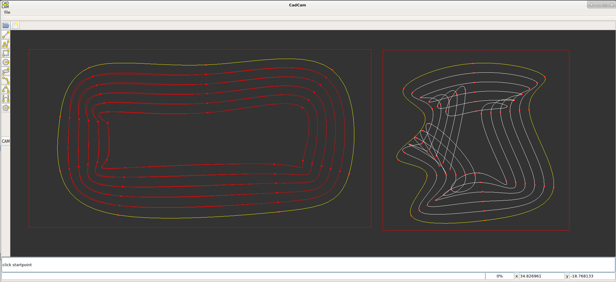
At the left you see double path's in red. This is visible when zooming in the picture.
This is a preview if a spline is played from left to right and visa versa.
So important is, when changing the contour direction for a spline from cw to ccw, interpolate the spline backwards.
About the tool radius compensation, the solution for this problem is quite simple.
If the machine has a active tool compensation, we interpolate the spline as an offset linestrip.
For this linestrip i will make a interpolation model, that we can use to get it right.
The linestrip has to have a clean up function, when the lines are becoming less 0mm, they must be deleted and re-attached.
Okey so far so good !
Update:
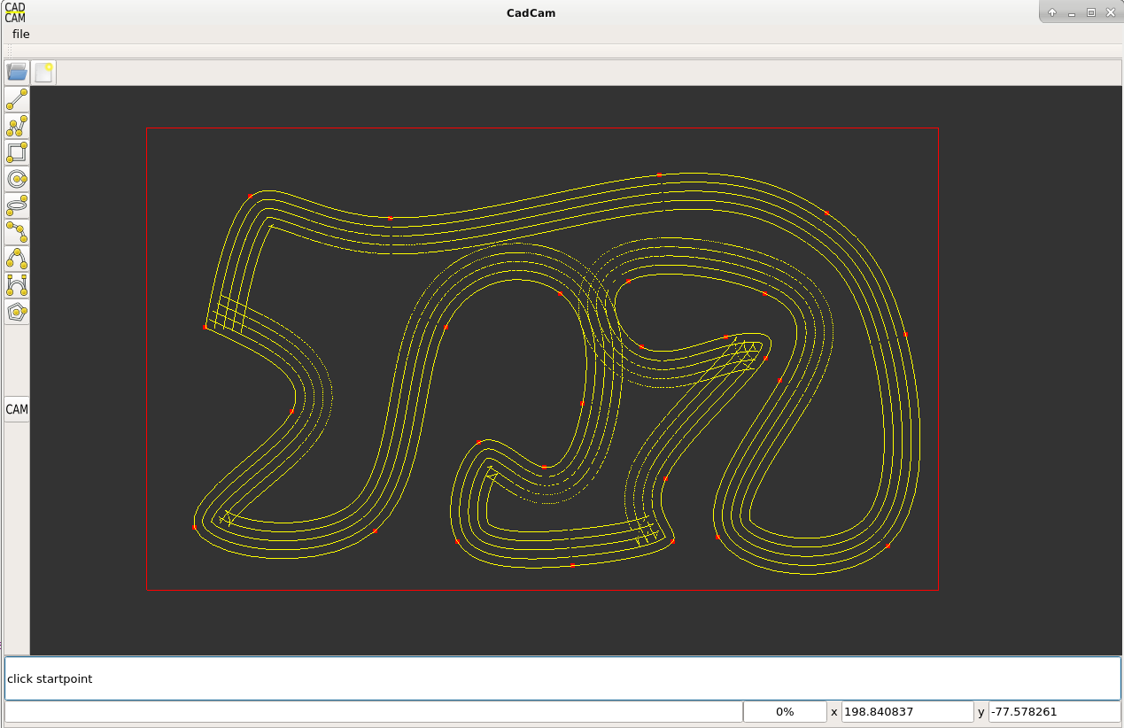
This is a spline_offset_as_linestrip. This is good. What we miss is a line-line interection to reconnect the offset path's.
For pockets we do a contour self intersect check, but that has nothing to do with this.
I was curious if G41 & G42 Cutter Compensation could be used with the new spline interpolation.
If we use a code like this :
G41.1 D10 (Dynamic Cutter Compensation on, left of programmed path)
G0 X0 Y0 (start of the spline)
F1500
G5.4 (start block)
X10 Y10 (first control point)
X100 Y100 (second control point)
X250 Y25 (etc)
X350 Y-20
X600 Y0
G5.5 (end block)
G40 (tool compensation off)
The red dots are controlpoints. Their offset is calculated at a precision of 0.001mm for each offsetted controlpoint.
At the left you see double path's in red. This is visible when zooming in the picture.
This is a preview if a spline is played from left to right and visa versa.
So important is, when changing the contour direction for a spline from cw to ccw, interpolate the spline backwards.
About the tool radius compensation, the solution for this problem is quite simple.
If the machine has a active tool compensation, we interpolate the spline as an offset linestrip.
For this linestrip i will make a interpolation model, that we can use to get it right.
The linestrip has to have a clean up function, when the lines are becoming less 0mm, they must be deleted and re-attached.
Okey so far so good !
Update:
This is a spline_offset_as_linestrip. This is good. What we miss is a line-line interection to reconnect the offset path's.
For pockets we do a contour self intersect check, but that has nothing to do with this.
Last edit: 6 years 4 months ago by Grotius.
Please Log in or Create an account to join the conversation.
Time to create page: 0.153 seconds