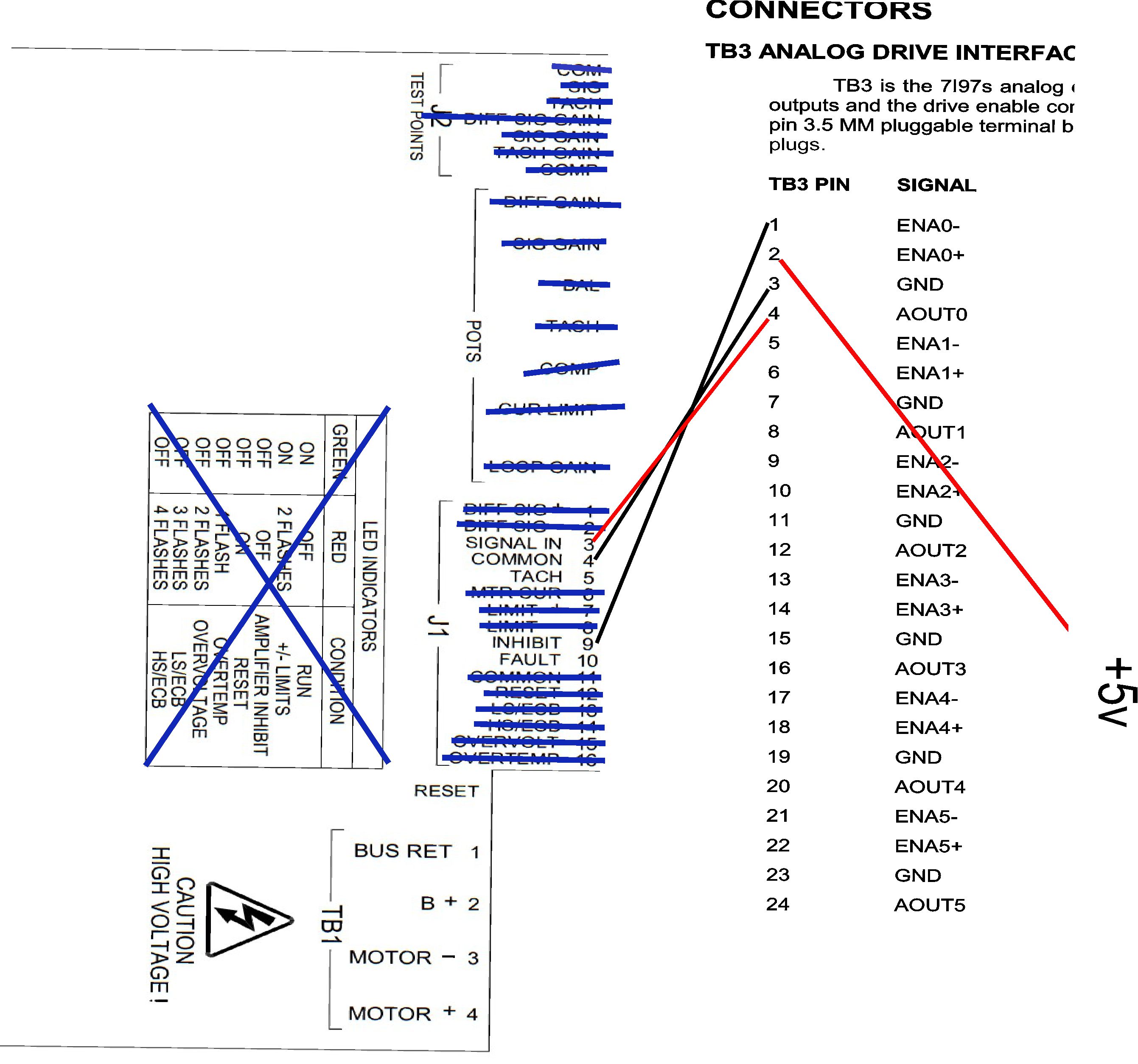
TB3 can only interface with the motor drives, not directly to the motor. What motor drives are you using with your motors?
With regards to TB3, each block of 4 terminals handles 2 functions: (1) enabling/disabling the motor or spindle drive, (2) sending the control signal to the motor drive in the form of a continuously variable voltage between -10 and +10 VDC. A signal of 0 volts tells the motor to stop.
ENA- and ENA+ provide the enable/disable signal to the drive. The wiring of these terminals depends on the type of enable signal your drives need.
- If your drive needs +5 VDC to enable ("active high enable") then ENA+ is wired to a +5 VDC voltage source (TB4 pin 21 or 22) and ENA- is wired to the drive enable pin.
- If your drive needs a ground signal to enable ("active low enable") then ENA- is wired to a ground (TB4 pin 23 or 24) and ENA+ is wired to the drive enable pin.
GND and AOUT are for the control signal. AOUT would typically be wired to the drive "SIGNAL+" or equivalent signal name used for your specific drive. GND would go to the drive "SIGNAL-" or equivalent. Additionally, I highly recommend that you use a shielded cable for the drive control signal. With a shielded cable, the shield is also connected to the GND terminal next to AOUT on the 7I97 but the shield is left unconnected at the drive end of the cable. If you don't have a shielded cable, twist the two wires together at a twist pitch of 1 to 1.5 inches for the whole length. Avoid running the drive control signal wires alongside high current wiring, AC wiring or wires that control solenoids.
RT