- Configuring LinuxCNC
- Basic Configuration
- Pncconf, howto setup for Mesa 5i25, 6i25, 7i92 using parallel port/BOB/G540
Pncconf, howto setup for Mesa 5i25, 6i25, 7i92 using parallel port/BOB/G540
- tommylight
-
 Topic Author
- Online
- Moderator
-

Less
More
- Posts: 21662
- Thank you received: 7400
28 Apr 2020 14:55 - 29 Apr 2020 10:16 #165983
by tommylight
Pncconf, howto setup for Mesa 5i25, 6i25, 7i92 using parallel port/BOB/G540 was created by tommylight
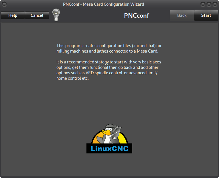
Noticed that pncconf guide in the docs still has old pictures of the EMC2 version, so i will try to gather that info and add as needed with new pictures.
Pncconf can be accessed from the main menu>cnc>pncconf, that will bring up this window: (colours may vary)
-
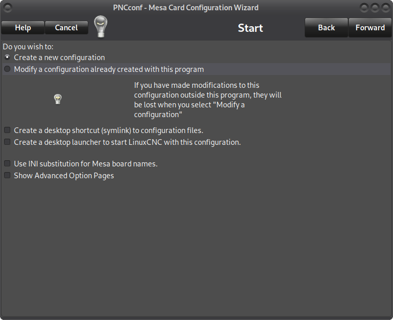
Click on start to get to the next screen, here you can choose to create a new config or edit an existing one. Also the options to create a desktop shortcut and a desktop launcher should be chosen so it is easy to later start the configuration from the desktop and also have a link to those configuration files:
-
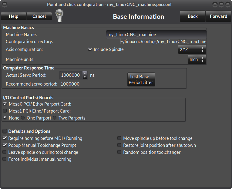
Click on forward, write a name for your configuration, usually a machine name or however you would like it to be called in the Machine Name field, if you do not have a spindle that can be remotely controlled or a 3D printer, plasma, etc untick the "include spindle", select the geometry of the machine as XYZ for 3 axis ( also choose this for tandem axis or a machine that has two motors for the same axis, usually on both sides of the gantry, do not choose XYZA for this ), XYZA for a 4 axis machine or XZ for a lathe and choose units in MM or Inch.
-
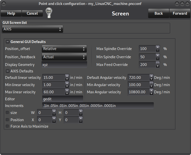
Click forward, choose from the "GUI screen list" if you would like to have Axis or Gmoccapy or another graphical user interface, change default linear velocity and max linear velocity to what your machine should be able to handle, leave the rest as is:
-
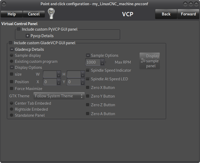
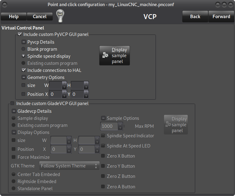
Click forward, here you can choose if the spindle speed should be added to the GUI, fist picture is without it, the second has "Virtual Control Panel" (VCP) and "spindle speed display" and "include connections to hal" ticked.
-
Click forward, this is where you choose the type of Mesa board and daughterboard if you have any, no daughterboard is used in this tutorial, choose "5i25 internal data" for Mesa 5i25 or 6i25, choose "7i92 internal data" for 7i92 and also set the address same as the board ( default is 192.168.1.121 so no changes there, but if you moved the jumper to set the board at 10.10.10.10 write that in the address field ), choose the firmware - in this case for BOB or G540 choose "G540x2" and click on "accept components changes":
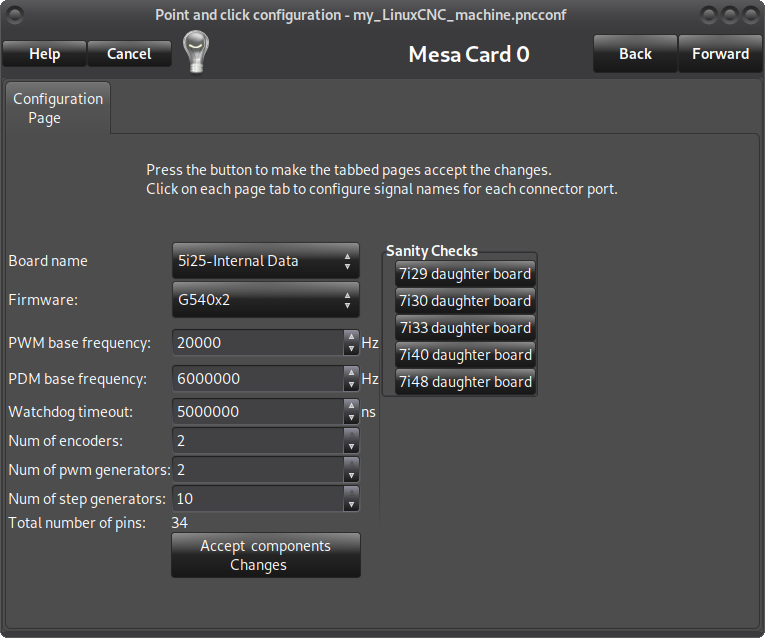
This will add two more tabs named "I/O connector 2" and "I/O connector 3", set the number of encoders to 0, the number of PWM generators to 1 if you have a PWM controlled spindle or to 0 if you do not have one, set the number of stepgens to 3 for a 3 axis machine or 4 for a 4 axis or tandem machine, click on "accept components changes" again :

continued on the next post
Pncconf can be accessed from the main menu>cnc>pncconf, that will bring up this window: (colours may vary)
-
Click on start to get to the next screen, here you can choose to create a new config or edit an existing one. Also the options to create a desktop shortcut and a desktop launcher should be chosen so it is easy to later start the configuration from the desktop and also have a link to those configuration files:
-
Click on forward, write a name for your configuration, usually a machine name or however you would like it to be called in the Machine Name field, if you do not have a spindle that can be remotely controlled or a 3D printer, plasma, etc untick the "include spindle", select the geometry of the machine as XYZ for 3 axis ( also choose this for tandem axis or a machine that has two motors for the same axis, usually on both sides of the gantry, do not choose XYZA for this ), XYZA for a 4 axis machine or XZ for a lathe and choose units in MM or Inch.
-
Click forward, choose from the "GUI screen list" if you would like to have Axis or Gmoccapy or another graphical user interface, change default linear velocity and max linear velocity to what your machine should be able to handle, leave the rest as is:
-
Click forward, here you can choose if the spindle speed should be added to the GUI, fist picture is without it, the second has "Virtual Control Panel" (VCP) and "spindle speed display" and "include connections to hal" ticked.
-
Click forward, this is where you choose the type of Mesa board and daughterboard if you have any, no daughterboard is used in this tutorial, choose "5i25 internal data" for Mesa 5i25 or 6i25, choose "7i92 internal data" for 7i92 and also set the address same as the board ( default is 192.168.1.121 so no changes there, but if you moved the jumper to set the board at 10.10.10.10 write that in the address field ), choose the firmware - in this case for BOB or G540 choose "G540x2" and click on "accept components changes":
This will add two more tabs named "I/O connector 2" and "I/O connector 3", set the number of encoders to 0, the number of PWM generators to 1 if you have a PWM controlled spindle or to 0 if you do not have one, set the number of stepgens to 3 for a 3 axis machine or 4 for a 4 axis or tandem machine, click on "accept components changes" again :
continued on the next post
Attachments:
Last edit: 29 Apr 2020 10:16 by tommylight. Reason: Wrong title !
The following user(s) said Thank You: BigJohnT, DoWerna
Please Log in or Create an account to join the conversation.
- tommylight
-
Topic Author
- Online
- Moderator
-
Less
More
- Posts: 21662
- Thank you received: 7400
28 Apr 2020 14:55 - 28 Apr 2020 15:24 #165984
by tommylight
Replied by tommylight on topic Pncconf, howto setup for Mesa 5i25, 6i25, 7i92 using parallel port/BOB/G540
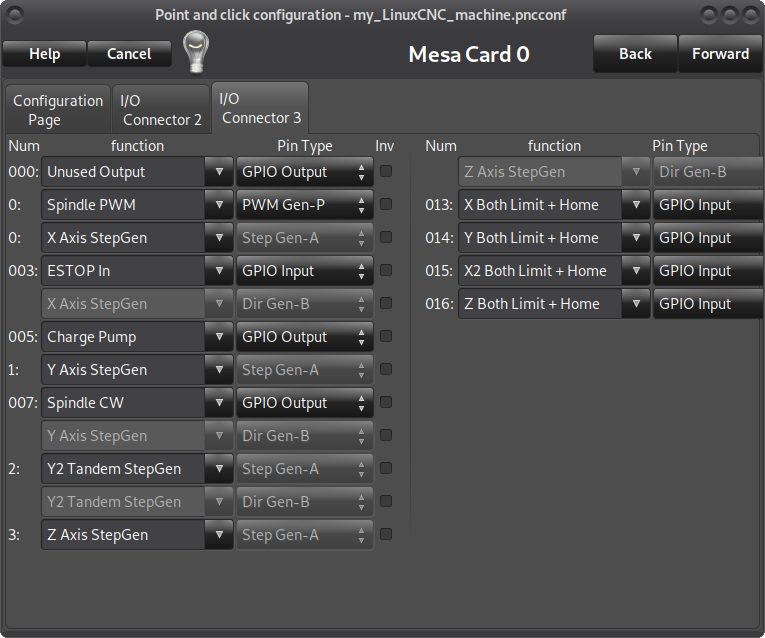
Click on the "I/O connector 3" and select the inputs and output to fit your hardware, but keep in mind that the numbers in front of the pins are not directly related to a D25 pinout on BOB or G540, so here is an example of how it should be for G540 with a charge pump and an E-stop:
-
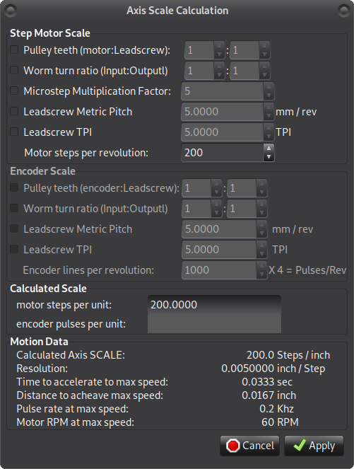
Click on forward, click on "calculate scale" :
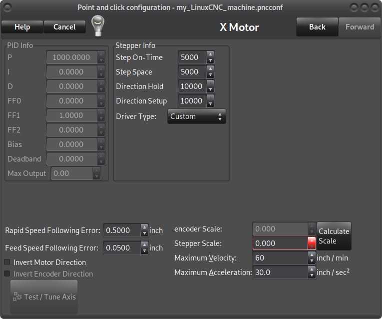
If you have a pulley reduction, tick in front of it and set the values to match your gearing, or enter the exact number of teeth on the motor pulley and on the other leadscrew, if using direct motor drive do not tick this.
If you have a worm gear, tick in front of it and enter the reduction ratio,
If you are using drives with microstepping, enter the microstepping value here after ticking in front of it,
Tick in front of either "leadscrew metric pitch" OR "leadscrew TPI" and enter how much the machine moves for one turn of the screw
For direct drive where the pulley is mounted on the motor shaft and driving the main belt, tick only microstepping if using it and either "leadscrew metric pitch" OR "leadscrew TPI" and enter the distance the machine travels for one full turn of the motor, example: 20 tooth GT2 pulley does 40mm for one turn, so enter 40 in the "leadscrew metric pitch".
Click apply:
-
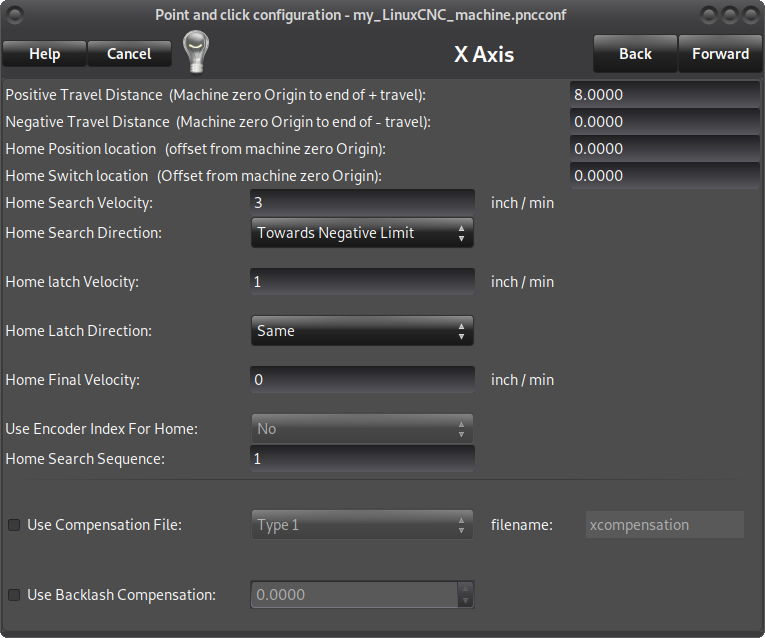
Click forward, this is where you set the distance for the X axis only, travel distance, homing, limits, etc. Set the positive travel distance to what your machine X axis can travel, if unsure leave the rest as is.
This has to be done for all the axis on their respective settings windows and they will be presented as you move forward. :
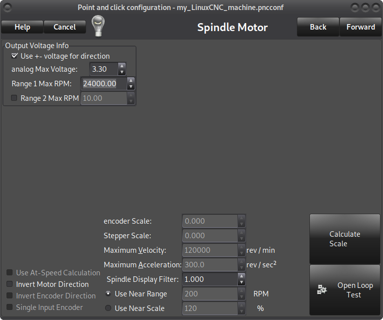
Click forward, set the other axis as you are presented, then you get to the spindle settings screen, here untick "use +- voltage for direction" and set the voltage to 5 (3.3 shown on screenshot) and set the max speed the spindle can do :
-
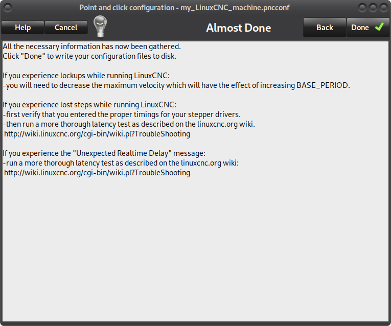
Click forward, and click Done, Yes.
-
Now you can start that configuration from the desktop and check if everything is working.
regards,
Tom
-
Click on forward, click on "calculate scale" :
If you have a pulley reduction, tick in front of it and set the values to match your gearing, or enter the exact number of teeth on the motor pulley and on the other leadscrew, if using direct motor drive do not tick this.
If you have a worm gear, tick in front of it and enter the reduction ratio,
If you are using drives with microstepping, enter the microstepping value here after ticking in front of it,
Tick in front of either "leadscrew metric pitch" OR "leadscrew TPI" and enter how much the machine moves for one turn of the screw
For direct drive where the pulley is mounted on the motor shaft and driving the main belt, tick only microstepping if using it and either "leadscrew metric pitch" OR "leadscrew TPI" and enter the distance the machine travels for one full turn of the motor, example: 20 tooth GT2 pulley does 40mm for one turn, so enter 40 in the "leadscrew metric pitch".
Click apply:
-
Click forward, this is where you set the distance for the X axis only, travel distance, homing, limits, etc. Set the positive travel distance to what your machine X axis can travel, if unsure leave the rest as is.
This has to be done for all the axis on their respective settings windows and they will be presented as you move forward. :
Click forward, set the other axis as you are presented, then you get to the spindle settings screen, here untick "use +- voltage for direction" and set the voltage to 5 (3.3 shown on screenshot) and set the max speed the spindle can do :
-
Click forward, and click Done, Yes.
-
Now you can start that configuration from the desktop and check if everything is working.
regards,
Tom
Last edit: 28 Apr 2020 15:24 by tommylight. Reason: reserved
Please Log in or Create an account to join the conversation.
- cmorley
- Offline
- Moderator
-
Less
More
- Posts: 7317
- Thank you received: 2147
29 Apr 2020 02:16 #166051
by cmorley
Replied by cmorley on topic Pncconf, howto setup for Mesa 5i25, 6i25, 7i92 using parallel port/BOB/G540
Need to change the title to pncconf...
The following user(s) said Thank You: tommylight
Please Log in or Create an account to join the conversation.
- bbsr_5a
- Offline
- Platinum Member
-

Less
More
- Posts: 544
- Thank you received: 106
29 Apr 2020 07:00 #166057
by bbsr_5a
Replied by bbsr_5a on topic Pncconf, howto setup for Mesa 5i25, 6i25, 7i92 using parallel port/BOB/G540
there is also a ready to use/test config in the config treads
it is not clear on the hardware side what he actuelly uses
on 7i92 make shure you got a good 5V supply otherwise you may see trouble even on Power LED on
also a realy good networkcable double shielded is a must have to get full comunication
it is not clear on the hardware side what he actuelly uses
on 7i92 make shure you got a good 5V supply otherwise you may see trouble even on Power LED on
also a realy good networkcable double shielded is a must have to get full comunication
Please Log in or Create an account to join the conversation.
- tommylight
-
Topic Author
- Online
- Moderator
-
Less
More
- Posts: 21662
- Thank you received: 7400
29 Apr 2020 10:18 #166071
by tommylight
Glasses do not help much when the brain is on leave !")
Replied by tommylight on topic Pncconf, howto setup for Mesa 5i25, 6i25, 7i92 using parallel port/BOB/G540
Thank you Chris, this is what Phill was on about, but i checked it several times and did not see it !Need to change the title to pncconf...
Glasses do not help much when the brain is on leave !
Please Log in or Create an account to join the conversation.
- ericg
- Offline
- Premium Member
-

Less
More
- Posts: 138
- Thank you received: 10
31 Jul 2020 00:39 #176588
by ericg
Replied by ericg on topic Pncconf, howto setup for Mesa 5i25, 6i25, 7i92 using parallel port/BOB/G540
I know this thread is a bit old but I just came across it and thought it would be handy to follow for my setup which is also a 5i25/G540 combo.
I noticed however that the I/O pins on your screenshot for I/O3 is different to mine, so some guidance would be appreciated on how to set mine up. For example according to my readhmid, Z step is pin 6 on the parallel port which is mapped to I/O 9 internally but I see no I/O 9 in my I/O3 page. Is there a later 5i25_G540 firmware I should flash?
I have attached an image of my I/O 3 page and what readhmid gives me
your help in understanding this is appreciated
Eric
Please Log in or Create an account to join the conversation.
- PCW
-

- Away
- Moderator
-
Less
More
- Posts: 17931
- Thank you received: 5255
31 Jul 2020 04:49 #176601
by PCW
Replied by PCW on topic Pncconf, howto setup for Mesa 5i25, 6i25, 7i92 using parallel port/BOB/G540
The I/O for the stepgen is not available so if the mesaflash readhmid command shows
stepgen 2 on pins 9 and 10 and you select stepgen 2 to drive the Z axis you should be
fine
stepgen 2 on pins 9 and 10 and you select stepgen 2 to drive the Z axis you should be
fine
Please Log in or Create an account to join the conversation.
- ericg
- Offline
- Premium Member
-
Less
More
- Posts: 138
- Thank you received: 10
31 Jul 2020 06:23 - 31 Jul 2020 06:25 #176606
by ericg
Replied by ericg on topic Pncconf, howto setup for Mesa 5i25, 6i25, 7i92 using parallel port/BOB/G540
Thanks for the reply Rodw, OK I see .. i/o 0 is X axis (0), i/o 1 is Y axis (1) and i/o 2 is z axis (2), and the rest is mapped as per readhmid. is this correct?, also with my fiddling I no longer have the spindle pages showing, I go from Z axis to done and the pyvcp panel shows seperately?.. quite the learning curve
BTW I also posted this similar post on the PncConf page as I wasn't sure if older posts got read.
BTW I also posted this similar post on the PncConf page as I wasn't sure if older posts got read.
Last edit: 31 Jul 2020 06:25 by ericg. Reason: added info
Please Log in or Create an account to join the conversation.
- tommylight
-
Topic Author
- Online
- Moderator
-
Less
More
- Posts: 21662
- Thank you received: 7400
31 Jul 2020 08:14 #176618
by tommylight
Replied by tommylight on topic Pncconf, howto setup for Mesa 5i25, 6i25, 7i92 using parallel port/BOB/G540
You mean PCW.Thanks for the reply Rodw,
Please Log in or Create an account to join the conversation.
- ericg
- Offline
- Premium Member
-
Less
More
- Posts: 138
- Thank you received: 10
31 Jul 2020 08:16 #176621
by ericg
Replied by ericg on topic Pncconf, howto setup for Mesa 5i25, 6i25, 7i92 using parallel port/BOB/G540
My apologies PCW, I was reading too many posts at once
Please Log in or Create an account to join the conversation.
- Configuring LinuxCNC
- Basic Configuration
- Pncconf, howto setup for Mesa 5i25, 6i25, 7i92 using parallel port/BOB/G540
Time to create page: 0.452 seconds