7i76e use outputs to toggle motor enable
- pCNC
- Offline
- New Member
-

Less
More
- Posts: 14
- Thank you received: 7
12 Jan 2022 18:37 #231578
by pCNC
7i76e use outputs to toggle motor enable was created by pCNC
Hi,
I'm using a mesa 7i76e to drive a machine (XYYZ) with 4 servo's with integrated controllers that accept STEP/DIR.
The motors/drivers/controllers have an Enable input and Alarm and PED (position reached) outputs.
I am planning to use the Alarm outputs to trigger a(n e-)stop if one of the motors goes into error, to force manual re-enable and re-home, if it occurs.
With the HAL tutorial I can probably figure out how to do that.
What I'm trying to figure out at the moment, is how I can elegantly reset the motor when they are in error.
At the moment this is done by pulling the plug that connects the motor power supply to mains....
The Enable input of the motor resets the alarm when I put 5V on it, so that seems promising.
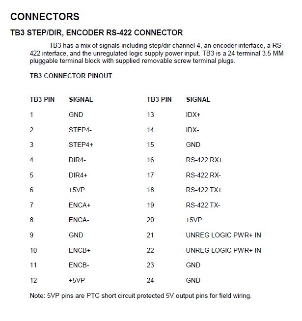
I'm using 4 of the 5 stepper possible stepper drivers, so I should have the 4 5V outputs I need on TB3.
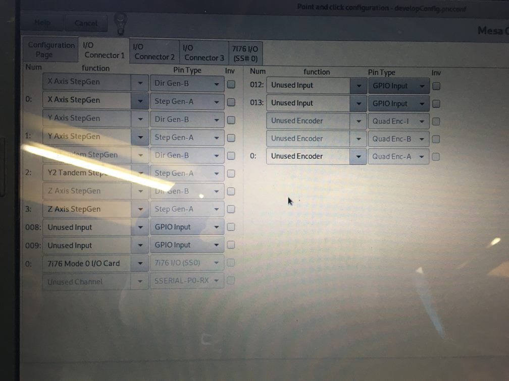
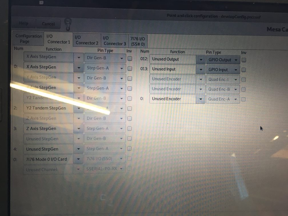
They are numbered 008, 009, 012 and 013. The latter two are also available if I tell the configuration I use 5 stepgens.
My problem is that I can't map them to physical pins using documentation or measurements.
A picture of the configuration page and the pin function according to the documentation is attached.
What I have tried so far is:
- Setting the 4 pins to GPIO-OUTPUT
- Define them as DigitalOut0 to 3, and try to toggle them with hal show, but I couldn't get the commands right
- Define them some of them as "Force Pin True", in different combinations, and measure the pins each time to try and derive what is what.
Neither of these approaches have lead to information I can use.
Is there anyone here that knows which physical pins to the ones I can configure in the software?
Or am I on the wrong track for controlling these enables?
Thanks for the help,
P
I'm using a mesa 7i76e to drive a machine (XYYZ) with 4 servo's with integrated controllers that accept STEP/DIR.
The motors/drivers/controllers have an Enable input and Alarm and PED (position reached) outputs.
I am planning to use the Alarm outputs to trigger a(n e-)stop if one of the motors goes into error, to force manual re-enable and re-home, if it occurs.
With the HAL tutorial I can probably figure out how to do that.
What I'm trying to figure out at the moment, is how I can elegantly reset the motor when they are in error.
At the moment this is done by pulling the plug that connects the motor power supply to mains....
The Enable input of the motor resets the alarm when I put 5V on it, so that seems promising.
I'm using 4 of the 5 stepper possible stepper drivers, so I should have the 4 5V outputs I need on TB3.
They are numbered 008, 009, 012 and 013. The latter two are also available if I tell the configuration I use 5 stepgens.
My problem is that I can't map them to physical pins using documentation or measurements.
A picture of the configuration page and the pin function according to the documentation is attached.
What I have tried so far is:
- Setting the 4 pins to GPIO-OUTPUT
- Define them as DigitalOut0 to 3, and try to toggle them with hal show, but I couldn't get the commands right
- Define them some of them as "Force Pin True", in different combinations, and measure the pins each time to try and derive what is what.
Neither of these approaches have lead to information I can use.
Is there anyone here that knows which physical pins to the ones I can configure in the software?
Or am I on the wrong track for controlling these enables?
Thanks for the help,
P
Attachments:
Please Log in or Create an account to join the conversation.
- PCW
-

- Away
- Moderator
-

Less
More
- Posts: 17996
- Thank you received: 5283
12 Jan 2022 19:23 #231588
by PCW
Replied by PCW on topic 7i76e use outputs to toggle motor enable
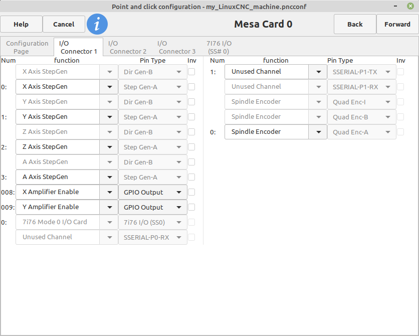
Stepgen 4 outputs would be GPIO bits
008 (Dir4+ and DIr4-) and 009 (Step4+ and Step4-)
So you need to set these as outputs in pncconf and then connect
them to the correct signals, something like this:
008 (Dir4+ and DIr4-) and 009 (Step4+ and Step4-)
So you need to set these as outputs in pncconf and then connect
them to the correct signals, something like this:
Attachments:
Please Log in or Create an account to join the conversation.
- tommylight
-

- Offline
- Moderator
-
Less
More
- Posts: 21764
- Thank you received: 7438
13 Jan 2022 07:08 #231635
by tommylight
Replied by tommylight on topic 7i76e use outputs to toggle motor enable
I have LAM Tehnologies drives with fault outputs, enable wired as usual in LinuxCNC, the fault inputs are wired to
joint.n.amp.fault
Or similar, nothing esle is required as when fault is triggered the drives are disabled and enabling them clears the fault.
Tested this extensively, it is that simple.
joint.n.amp.fault
Or similar, nothing esle is required as when fault is triggered the drives are disabled and enabling them clears the fault.
Tested this extensively, it is that simple.
The following user(s) said Thank You: chili023
Please Log in or Create an account to join the conversation.
- rodw
-

- Offline
- Platinum Member
-

Less
More
- Posts: 12054
- Thank you received: 4114
13 Jan 2022 07:33 #231638
by rodw
Are you sure you need 5 volts? Most fault signals I've seen are isolated so will support 24 volt inputs.
But you probably can't set them up in pncconf..
Replied by rodw on topic 7i76e use outputs to toggle motor enable
Tommy is right here. This is how to do it.I have LAM Tehnologies drives with fault outputs, enable wired as usual in LinuxCNC, the fault inputs are wired to
joint.n.amp.fault
Or similar, nothing esle is required as when fault is triggered the drives are disabled and enabling them clears the fault.
Tested this extensively, it is that simple.
Are you sure you need 5 volts? Most fault signals I've seen are isolated so will support 24 volt inputs.
But you probably can't set them up in pncconf..
The following user(s) said Thank You: tommylight, chili023
Please Log in or Create an account to join the conversation.
- pCNC
- Offline
- New Member
-
Less
More
- Posts: 14
- Thank you received: 7
14 Jan 2022 18:55 #231787
by pCNC
Ah, the Dir+/- and Step+/- are still linked ofcourse, explains the measurement results I got. And now I get what these Amplifier outputs are for
The fault can indeed sink or source 24V (luckily), so they are already connected to the 24V inputs.
When I have something working I'll share here")
Replied by pCNC on topic 7i76e use outputs to toggle motor enable
Stepgen 4 outputs would be GPIO bits
008 (Dir4+ and DIr4-) and 009 (Step4+ and Step4-)
Ah, the Dir+/- and Step+/- are still linked ofcourse, explains the measurement results I got. And now I get what these Amplifier outputs are for
Cool, going to try that out this weekend.I have LAM Tehnologies drives with fault outputs, enable wired as usual in LinuxCNC, the fault inputs are wired to
joint.n.amp.fault
Or similar, nothing esle is required as when fault is triggered the drives are disabled and enabling them clears the fault.
Tested this extensively, it is that simple.
The documentation of my drives is somewhat ambiguous on what their enable inputs can handle, therefore I'd rather be safe than sorry and use the 5V for that.Are you sure you need 5 volts? Most fault signals I've seen are isolated so will support 24 volt inputs.
But you probably can't set them up in pncconf..
The fault can indeed sink or source 24V (luckily), so they are already connected to the 24V inputs.
When I have something working I'll share here
Please Log in or Create an account to join the conversation.
- rodw
-
- Offline
- Platinum Member
-
Less
More
- Posts: 12054
- Thank you received: 4114
14 Jan 2022 20:54 #231794
by rodw
Replied by rodw on topic 7i76e use outputs to toggle motor enable
So sounds like if you revise your hal to use amplifier-enable the fault side is done!
With the enable, what I did was steal +5v from one of the stepgens and use a relay to switch this to the enable from the estop out signal. eg. such that hitting estop would disable the drives. I just used the one circuit for all drive enables.
That way, pressing estop disables the drive and if out of estop they are enabled.
Please Log in or Create an account to join the conversation.
- pCNC
- Offline
- New Member
-
Less
More
- Posts: 14
- Thank you received: 7
15 Jan 2022 12:53 #231888
by pCNC
Replied by pCNC on topic 7i76e use outputs to toggle motor enable
As easy as promised
I've set up output 008 on I/O Connector 1 as "Machine Is Enabled" in pncConf, and connected pin 4 of TB3 (DIR4-) to all the motor enables, so they are toggled all together.
The alarm signals are now linked to joint.N.amp-fault-in, using the attached custom_postgui.hal.
Now when one of the motors goes into error, Linuxcnc shows an joint amplifier error and takes away the enable for all joints. When I toggle the enable, everything can be jogged/homed again, without power cycling the drives.
The error is reset almost immediately (at least way before I can go look for a red light) instead of when I toggle the enable again, so either something is slow (my very old laptop for instance) or the driver responds a little differently than I was expecting.
It was confusing for a moment, but it is workable and I can continue working from here
Thanks for the tips!
Attachments:
Please Log in or Create an account to join the conversation.
- pCNC
- Offline
- New Member
-
Less
More
- Posts: 14
- Thank you received: 7
15 Jan 2022 12:54 #231889
by pCNC
Replied by pCNC on topic 7i76e use outputs to toggle motor enable
Oops, forgot to insert the attachment...
Attachments:
The following user(s) said Thank You: tommylight
Please Log in or Create an account to join the conversation.
- strahlensauger
-

- Offline
- Elite Member
-

Less
More
- Posts: 195
- Thank you received: 66
21 Jan 2022 12:45 - 21 Jan 2022 15:28 #232633
by strahlensauger
Replied by strahlensauger on topic 7i76e use outputs to toggle motor enable
I own JMC ihvs57 servos, in the documentation I find:
"Enabling signal: This input signal is used to enable or prohibit; In addition, it can be used to clear the drive alarm. When ENA + is connected to +5 V, ENA-is connected to low power, the drive will cut off the current of each phase of the motor so that the motor is in a free state, where the pulse is not responded and the alarm can be cleared; When this function is not required, the energy signal end is suspended."
So the ENA+ only needs a short pulse to clear the drive, I can't connect the output signal from the 7i76e directly to the ENA+, because it is always on, apart from that the servo accepts only 5 Volts.
In the discussion above the signal is always high on the enable-amp output as far as I understood, any ideas how to connect the ENA+ input in my case?
I could just put a physical push-button inbetween a 5 Volt line, but I would prefer clearing the servos directly from Linuxcnc, something like a button in pyvcp. (Does a push button exist)?
Last edit: 21 Jan 2022 15:28 by strahlensauger.
Please Log in or Create an account to join the conversation.
- chris@cnc
- Offline
- Platinum Member
-
Less
More
- Posts: 529
- Thank you received: 140
21 Jan 2022 14:35 #232642
by chris@cnc
Replied by chris@cnc on topic 7i76e use outputs to toggle motor enable
I recommend to use the ENA signal as high bit to enable the drive after E-stop or alarm. if you have any alarm on this easy drive it’s have a reason and could not done by reset. usually restarts machine necessary.
The following user(s) said Thank You: strahlensauger
Please Log in or Create an account to join the conversation.
Time to create page: 0.322 seconds