Probe Basic Help
- natholego11
-
 Topic Author
- Offline
- Senior Member
-

- Posts: 71
- Thank you received: 4
I recently wanted to take my linux cnc experience to the next level. so I started investigating what it would take to get Probe_basic to work. I followed "dr dflo's" build and his site as some helpful links to get all the OS's and updates in linux and ultimately probe basic running.
here is where I stand.
I got debian 10 installed, linuxcnc 2.8 downloaded and running and finally probe basic installed and the sim runs fine.
that being the case I ran PCconfig and got the mesa card working and have a functioning Axis gui that moves the machine just how I want it. what I did after that was copied most of the (what I thought was) relavant text out of the probe basic sim ini file into my ini file, and renamed the "display = axis" to display = probe_basic.
naturally im getting an error. I did some searching and realized that I needed all the config files and subroutines in the same folder as my config files are in, so I copied those over but still nothing.
my question is this: what is the process of changing the gui from Axis to Probe_basic? is it as simple as just changing the "display =" from one to the other, or is it more complex than that? Also, I didnt see a HAL file for probe_basic that tied all the pins from the 7i96 to the correct hal pins. attached is my whole folder, for my machine.
let me know how much of an idiot I am for some of the assumptions I have made

Please Log in or Create an account to join the conversation.
- spumco
- Offline
- Platinum Member
-

- Posts: 2076
- Thank you received: 862
let me know how much of an idiot I am for some of the assumptions I have made
I think you're taking care of that yourself
")
If you can run the PB gui in simulation mode from the GUI chooser window, you're in good shape so far.
However, there are some other things that need to be changed in the INI and .hal files to get it working. I can't find the thread at the moment, but in the QtPyVCP forum is a thread where some kind soul posted his .hal file with comments showing what he had to change. It's more than just the DISPLAY section.
Have a look in the qtpyvcp and search around. I'll check back tonight and if you're still stuck I'll try to find that thread and let you know.
-Ralph
NOTE - might want to move this to qtpyvcp sub-forum
Please Log in or Create an account to join the conversation.
- tommylight
-

- Away
- Moderator
-

- Posts: 21573
- Thank you received: 7365
Please Log in or Create an account to join the conversation.
- spumco
- Offline
- Platinum Member
-
- Posts: 2076
- Thank you received: 862
NOTE - this assumes you have a working configuration using Axis or another basic GUI, as well as Probe Basic sim working.
forum.linuxcnc.org/qtpyvcp/41355-probe-b...on-vs-pncconf-how-to
Have a look halfway down the thread where Muzzer posts his INI file. I suggest you open a copy of this file, along with your working Axis file (and the original Probe Basic sim file). Use VS Code and have all three open at once - that's my strategy.
Then carefully (line by line) incorporate the various changes in to your INI file. Pay attention to the file locations called out in the INI file... you may have named a folder something different from the sim or Muzzer's example.
Obviously you don't want a lathe configuration, but I think you get the point.
Please Log in or Create an account to join the conversation.
- Lcvette
-

- Offline
- Moderator
-
- Posts: 1623
- Thank you received: 755
Thanks!
Chris
Please Log in or Create an account to join the conversation.
- natholego11
-
Topic Author
- Offline
- Senior Member
-
- Posts: 71
- Thank you received: 4
Please Log in or Create an account to join the conversation.
- natholego11
-
Topic Author
- Offline
- Senior Member
-
- Posts: 71
- Thank you received: 4
Thank you everybody!
EDIT:
After getting it running I noticed there are so many features. Thanks to everybody who worked on this GUI it really does enhance the linuxCNC experience.
a few questions.
1. after changing to incremental jog mode, how do you get back to continuous jog mode?
2. how do I connect the spindle encoder to the "DRO" on the GUI? my pins are all there in the HAL file, but im sure there is another file that needs one or more of the hal pins
3. when I am setting up my tool table and touching tools off, I have seen many people use the spindle nose as the reference, that being the case - Why do they do this? does my G59.3 have to be the machine home coordinates, otherwise itll miss the probe? what is the purpose of having the nose being the first thing you touch off?
Please Log in or Create an account to join the conversation.
- Lcvette
-
- Offline
- Moderator
-
- Posts: 1623
- Thank you received: 755
1. after changing to incremental jog mode, how do you get back to continuous jog mode?
in the ini:
INCREMENTS = JOG .1in .01in .001in .0001in
having the JOG entry in the increments ini line adds a jog button that is built into the increments widget. see the below thread for anything else you may have missed!
forum.linuxcnc.org/qtpyvcp/44889-probe-b...onfig-conversion-doc
2. how do I connect the spindle encoder to the "DRO" on the GUI? my pins are all there in the HAL file, but im sure there is another file that needs one or more of the hal pins.
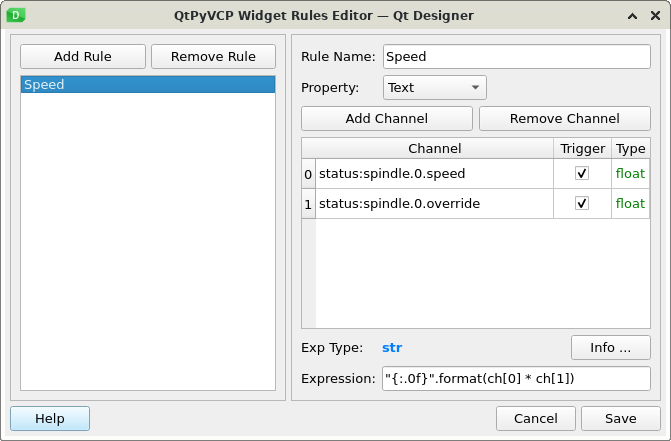
The darker (left side) spindle rpm dro in the lower main panel is the actual spindle speed taken from linuxcnc "speed" status. in the gui it is pulling data from linuxcnc STATUS: spindle.0.speed and is a float value. you should be able to connect your hal to feed this. you can see the dro widget rule for the readout below as well as the docs link to set you on the path on how to accomplish this:
linuxcnc.org/docs/html/config/python-int...spindle_dictionary_a

3. when I am setting up my tool table and touching tools off, I have seen many people use the spindle nose as the reference, that being the case - Why do they do this? does my G59.3 have to be the machine home coordinates, otherwise itll miss the probe? what is the purpose of having the nose being the first thing you touch off?
The spindle nose creates a repeatable gage line that all tools are offset against. because this never changes it ensures that all the stores offsets remain accurate. once the height has been established and stored in the touch off settings on the offsets page as (SPINDLE ZERO), you should be ok providing your tool setter is permanently mounted and your home switches are accurate. if they are not, you should remeasure the spindle zero height and enter prior to measuring new tools all while in the same running instance of linuxcnc. G59.3 is where the tool touch off position is stored. this is done so the user can see and verify the stored position in the offsets table.
the purpose for using the spindle gage line verse using the probe as a master tool, is to avoid those with large tool libraries having to remeasure all tools if the probe is crashed and a new tip installed which will effect its new tool length and as such any tools measured against the previous length offset of the probe. by the probe being a single tool with its own offset against the spindle nose, if it is changed and updated the new offset will still be accurate in relation to all other stored tools. this is the best way "in my opinion at least" to accomplish keeping everything consistent and compartmentalized to eliminate globally impacting the tool library in the event of a mishap. if this isn't the way you would like to have the touch off, the macros i wrote are in the subroutines folder and can be rewritten to suit. the button is tied to the macros file name and the other entries can be manipulated in the subroutine as you desire.
hope this helps!
Chris Polanski
Attachments:
Please Log in or Create an account to join the conversation.
- natholego11
-
Topic Author
- Offline
- Senior Member
-
- Posts: 71
- Thank you received: 4
2. how do I connect the spindle encoder to the "DRO" on the GUI? my pins are all there in the HAL file, but im sure there is another file that needs one or more of the hal pins.
The darker (left side) spindle rpm dro in the lower main panel is the actual spindle speed taken from linuxcnc "speed" status. in the gui it is pulling data from linuxcnc STATUS: spindle.0.speed and is a float value. you should be able to connect your hal to feed this. you can see the dro widget rule for the readout below as well as the docs link to set you on the path on how to accomplish this:
linuxcnc.org/docs/html/config/python-int...spindle_dictionary_a
im not exactly following what youre saying here, in the pyVCP on a normal Axis GUI the hal pins
"net spindle-vel-fb-rps => abs.0.in
net spindle-vel-fb-rps-abs abs.0.out"
are assigned to
" spindle-fb-rpm-abs-filtered => pyvcp.spindle-speed
net spindle-at-speed => pyvcp.spindle-at-speed-led"
and that shows up in the VCP.
do I use these same pins and just assign them to different values? or am i missing this completely?
Please Log in or Create an account to join the conversation.
- Lcvette
-
- Offline
- Moderator
-
- Posts: 1623
- Thank you received: 755
loadrt abs names=abs.spindle
loadrt lowpass names=lowpass.spindle
loadrt scale names=scale.spindle
loadrt near
addf scale.spindle servo-thread
addf abs.spindle servo-thread
addf lowpass.spindle servo-thread
addf near.0 servo-thread
#*******************
# SPINDLE S
#*******************
setp pid.s.Pgain [SPINDLE_9]P
setp pid.s.Igain [SPINDLE_9]I
setp pid.s.Dgain [SPINDLE_9]D
setp pid.s.bias [SPINDLE_9]BIAS
setp pid.s.FF0 [SPINDLE_9]FF0
setp pid.s.FF1 [SPINDLE_9]FF1
setp pid.s.FF2 [SPINDLE_9]FF2
setp pid.s.deadband [SPINDLE_9]DEADBAND
setp pid.s.maxoutput [SPINDLE_9]MAX_OUTPUT
setp pid.s.error-previous-target true
net spindle-index-enable <=> pid.s.index-enable
net spindle-enable => pid.s.enable
net spindle-vel-cmd-rpm => pid.s.command
net spindle-vel-fb-rpm-abs => pid.s.feedback
net spindle-output <= pid.s.output
# ---PWM Generator signals/setup---
setp hm2_7i92.0.7i77.0.1.analogout0-scalemax [SPINDLE_9]OUTPUT_SCALE
setp hm2_7i92.0.7i77.0.1.analogout0-minlim [SPINDLE_9]OUTPUT_MIN_LIMIT
setp hm2_7i92.0.7i77.0.1.analogout0-maxlim [SPINDLE_9]OUTPUT_MAX_LIMIT
net spindle-output => hm2_7i92.0.7i77.0.1.analogout0
net spindle-enable hm2_7i92.0.7i77.0.1.analogena
# ---Encoder feedback signals/setup---
setp hm2_7i92.0.encoder.00.counter-mode 0
setp hm2_7i92.0.encoder.00.filter 1
setp hm2_7i92.0.encoder.00.index-invert 0
setp hm2_7i92.0.encoder.00.index-mask 0
setp hm2_7i92.0.encoder.00.index-mask-invert 0
setp hm2_7i92.0.encoder.00.scale [SPINDLE_9]ENCODER_SCALE
net spindle-revs <= hm2_7i92.0.encoder.00.position
net spindle-vel-fb-rps <= hm2_7i92.0.encoder.00.velocity
net spindle-index-enable <=> hm2_7i92.0.encoder.00.index-enable
# ---setup spindle control signals---
net spindle-vel-cmd-rps <= spindle.0.speed-out-rps
net spindle-vel-cmd-rps-abs <= spindle.0.speed-out-rps-abs
net spindle-vel-cmd-rpm <= spindle.0.speed-out
net spindle-vel-cmd-rpm-abs <= spindle.0.speed-out-abs
net spindle-enable <= spindle.0.on
net spindle-cw <= spindle.0.forward
net spindle-ccw <= spindle.0.reverse
net spindle-brake <= spindle.0.brake
net spindle-revs => spindle.0.revs
net spindle-at-speed => spindle.0.at-speed
net spindle-vel-fb-rps => spindle.0.speed-in
net spindle-index-enable <=> spindle.0.index-enable
# ---Setup spindle at speed signals---
net spindle-vel-cmd-rps => near.0.in1
net spindle-vel-fb-rps => near.0.in2
##########################
net spindle-at-speed <= near.0.out
##########################
setp near.0.scale 1.000000
##########################
setp near.0.difference 5
##sets spindle-at-speed true
# Use ACTUAL spindle velocity from spindle encoder
# spindle-velocity bounces around so we filter it with lowpass
# spindle-velocity is signed so we use absolute component to remove sign
# ACTUAL velocity is in RPS not RPM so we scale it.
setp scale.spindle.gain 60
setp lowpass.spindle.gain 1.000000
net spindle-vel-fb-rps => scale.spindle.in
net spindle-fb-rpm scale.spindle.out => abs.spindle.in
net spindle-fb-rpm-abs abs.spindle.out => lowpass.spindle.in
net spindle-fb-rpm-abs-filtered lowpass.spindle.out
Please Log in or Create an account to join the conversation.