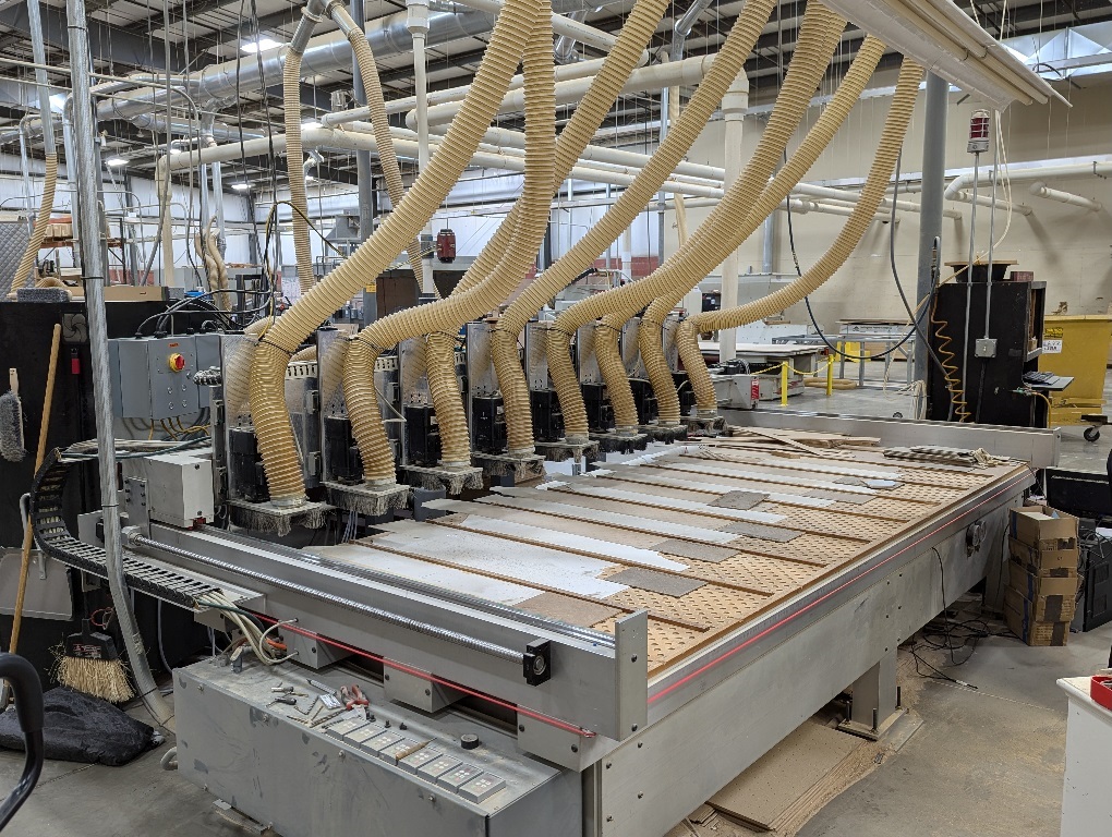
This 8 spindle gang router with 8 independent Z axis (using closed loop stepper motors), tandem servos for the Y axis gantry, and a servo on they X axis.
This machine has evolved a bit over time. It was my very first Linuxcnc(EMC2) retrofit. I have shared some details of it through the years. Here is a link to what it looked like when I was first setting it up on Linuxcnc.
forum.linuxcnc.org/38-general-linuxcnc-q...-help?start=50#11052
The machine originally only had 3 joints, with a single servo moving a large (2ft x 8ft) aluminum plate up and down via a centrally mounted lead screw. All 8 spindles were bolted to that plate with a hand actuated screw to fine tune each spindle's depth. The Y axis was moved by a set of helical rack and pinion gears on each end of the gantry, connected together by a 12ft long torque tube drive shaft, then a 12:1 belt reduction to the servo motor. The X axis was driven by a servo/lead screw combo. After 20years of use all of the linear components needed refreshed, so we decided to redesign most of it.
X axis received the least change, changing from a high lead lead screw connected to the servo via a belt reduction, to a new 25mm x 5mm lead ball screw directly coupled to the servo, and new linear ways.
Y axis, got new larger linear ways, and replaced the rack and pinions with two 25mm x 10mm lead ball screws and 2:1 belt reduction to the old Y and former Z servos.
For the Zs, I removed the large 3/4inch thick by 2ft x 8ft plate, cut off 8 pieces 5inch x 24inch and milled them to mount a pair of linear ways and a ball screw for each spindle and a NEMA 23 closed loop stepper motor for each.
Here is a link to a Google photo album containing some photos of the pieces I milled for each of the 8 Z-axis joints.
photos.app.goo.gl/Tx2oYkS272xBUMvZ7
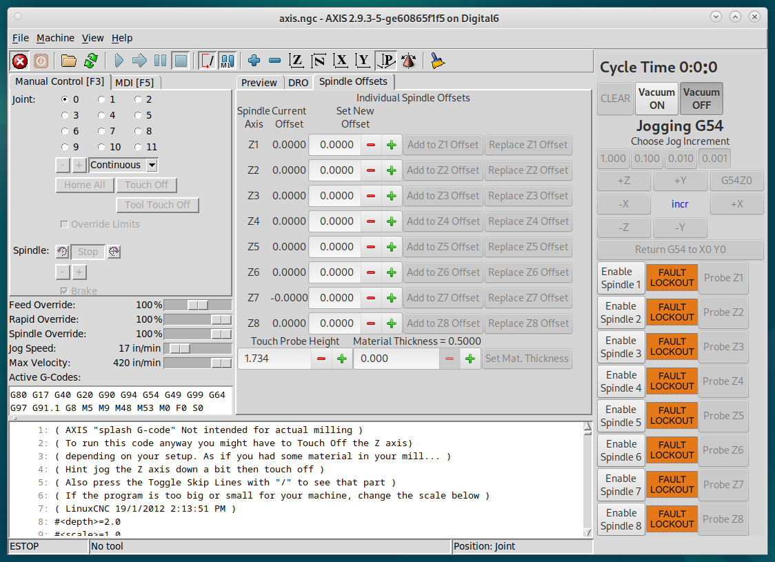
Then I'm attaching a copy of my config directory so others can see how I implemented the individual Z axis joints. The Z axis is set up as a dummy master joint that automatically homes. Each spindle joint is set up as an "extra" joint. There is a GladeVCP panel that lets the operator enable and disable each of the spindles. When a spindle is enabled, that spindle's Z-joint is connected to the dummy master's position plus a tool offset. When it is disabled the spindle's joint is moved back up to it's home position. This way only the spindles actually being used are ever moved with the Z axis.
There are also buttons on the Glade panel for tool probing routines for each of the spindle Z-axis. These disable all of the other spindle Z-axis and enable the one being probed, then sets the tool offset for that spindle according to the probe results.
Then I created a GladeVCP tab window for displaying and manipulating the tool offsets for each of the spindles.