- Configuring LinuxCNC
- Advanced Configuration
- (Solved) Index signal for Orient, G33.1, M19 with proximity sensor
(Solved) Index signal for Orient, G33.1, M19 with proximity sensor
- anton610
- Offline
- Senior Member
-

Less
More
- Posts: 40
- Thank you received: 7
24 Dec 2021 15:23 #229895
by anton610
Replied by anton610 on topic Index signal for Orient, G33.1, M19 with proximity sensor
Hi, thanks!
I'll try.
Is it a problem that i use a NC sensor? Or should i use a NO sensor?
BR
Anton
I'll try.
Is it a problem that i use a NC sensor? Or should i use a NO sensor?
BR
Anton
Please Log in or Create an account to join the conversation.
- PCW
-

- Offline
- Moderator
-

Less
More
- Posts: 17925
- Thank you received: 5251
24 Dec 2021 16:05 #229899
by PCW
Replied by PCW on topic Index signal for Orient, G33.1, M19 with proximity sensor
Either will work, the firmware senses the edge of index
so the polarity (NC or NO) only changes which edge
of the index pulse is detected.
so the polarity (NC or NO) only changes which edge
of the index pulse is detected.
Please Log in or Create an account to join the conversation.
- Henk
- Offline
- Platinum Member
-

Less
More
- Posts: 408
- Thank you received: 92
24 Dec 2021 16:26 #229901
by Henk
Replied by Henk on topic Index signal for Orient, G33.1, M19 with proximity sensor
In this case, your 0v from your proxy voltage decider circuit and the 0v of the mesa card must be connected.
Please Log in or Create an account to join the conversation.
- anton610
- Offline
- Senior Member
-
Less
More
- Posts: 40
- Thank you received: 7
25 Dec 2021 11:58 #229955
by anton610
Replied by anton610 on topic Index signal for Orient, G33.1, M19 with proximity sensor
Hello,
many thanks for the inputs.
I've connected the signal correct (ttl, 0v to GND), measuring gives me also the values (0v, 4,08v)
when i run the command M19 R15 Q4 i get the error:

when i run G33.1 Z10 K2 i get the error:

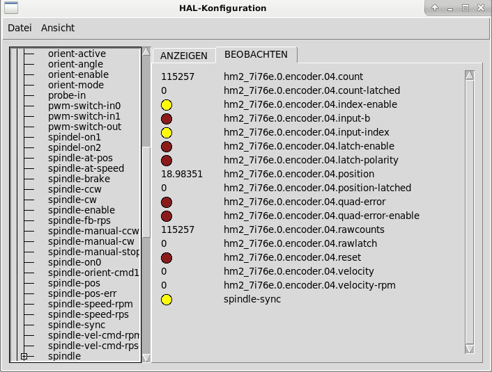
when the spindle is stopped my halshow is:
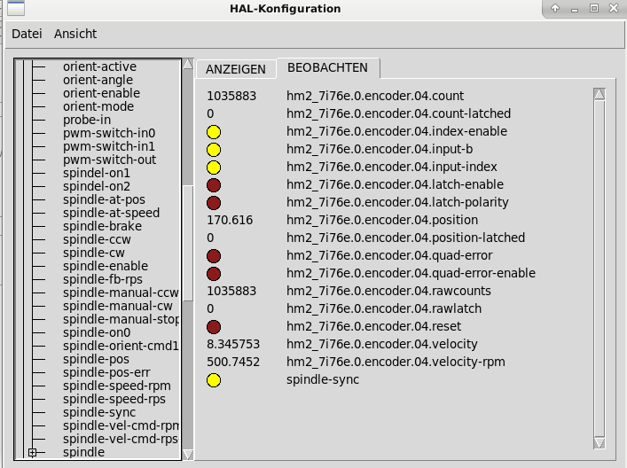
when the sindle is at 500rpm:
maybe the hal or ini is fault...
maybe someone can give ma a hint, where to look.
Many thanks!
BR Anton
many thanks for the inputs.
I've connected the signal correct (ttl, 0v to GND), measuring gives me also the values (0v, 4,08v)
when i run the command M19 R15 Q4 i get the error:
when i run G33.1 Z10 K2 i get the error:
when the spindle is stopped my halshow is:
when the sindle is at 500rpm:
maybe the hal or ini is fault...
maybe someone can give ma a hint, where to look.
Many thanks!
BR Anton
Attachments:
Please Log in or Create an account to join the conversation.
- Henk
- Offline
- Platinum Member
-
Less
More
- Posts: 408
- Thank you received: 92
25 Dec 2021 15:34 - 26 Dec 2021 03:32 #229962
by Henk
Replied by Henk on topic Index signal for Orient, G33.1, M19 with proximity sensor
ok, lets verify a couple of things first.
look at the pin spindle.0.revs in hal configuration. rotate the spindle by hand. this should go from 0 to 1, then reset back to 0 as you rotate. 0...>>...1 must equal exactly one rotation of your spindle...***edit: checked this on my machine, it counts up and down, does not stay between 0 and 1 as described above.
now, in MDI start the spindle with M3 S500, followed by G91 g33.1 z-20 k1 (assuming metric machine and G21 active) make sure that there is at enough space below the spindle to allow a -20mm move in Z direction.
if the spindle starts and runs, but no tapping action happens, your index signal is not detected, or the encoder direction is incorrect. for the latter you can swop A and B wiring, or you can set the encoder scale to -6071.428571428571 (negative) in your INI file.
It seems that your spindle is set up as a step/dir spindle. does it run? What functions are available in the drive? Position control mode selectable by an input signal to the drive?
I dont have any experiance with step/dir spindle setup. In your case, with the encoder on the motor and not on the spindle, you probably cannot use the drive orientation function and you should use Linuxcnc's orientation component, which seems to be the case looking at your hal file. Check the orientation mode, it needs to be set as either 0 or 1
henk
Last edit: 26 Dec 2021 03:32 by Henk.
Please Log in or Create an account to join the conversation.
- anton610
- Offline
- Senior Member
-
Less
More
- Posts: 40
- Thank you received: 7
25 Dec 2021 15:56 #229965
by anton610
Replied by anton610 on topic Index signal for Orient, G33.1, M19 with proximity sensor
Hello Henk!
Thanks for your time and quick reply!
spindle.0.revs is counting to plus and minus as i turn the spindle. it does not reset to 0. (maybe thats the problem)
I have is enough space to go -20 in Z, spindle is on the top position.
Spindle is not starting get the error: "spindle is not turning in G31"
When i turn the spindle, the encoder counts to plus in clock direction and to minus counter clock direction.
The spindle runs CW and CCW normally. I can set the speed by S command without a problem.
I run the spindle in position mode, velocity mode (0-10V) and torqe mode are also available.
BR Anton
Please Log in or Create an account to join the conversation.
- Henk
- Offline
- Platinum Member
-
Less
More
- Posts: 408
- Thank you received: 92
25 Dec 2021 16:22 - 26 Dec 2021 03:33 #229966
by Henk
Replied by Henk on topic Index signal for Orient, G33.1, M19 with proximity sensor
The spindle pos does not seem to be correct. And you need to get the spindle to run using M3/4.
**edit. spindle.0.revs counts up and down, doesnt stay between 0 and 1, this is correct, checked on my machine.
**edit. spindle.0.revs counts up and down, doesnt stay between 0 and 1, this is correct, checked on my machine.
Last edit: 26 Dec 2021 03:33 by Henk.
The following user(s) said Thank You: anton610
Please Log in or Create an account to join the conversation.
- anton610
- Offline
- Senior Member
-
Less
More
- Posts: 40
- Thank you received: 7
25 Dec 2021 16:29 #229968
by anton610
Replied by anton610 on topic Index signal for Orient, G33.1, M19 with proximity sensor
Hi,
Yes M3, M4 with S command works.
With "spindle pos" you mean the encoder direction?
Yes M3, M4 with S command works.
With "spindle pos" you mean the encoder direction?
Please Log in or Create an account to join the conversation.
- anton610
- Offline
- Senior Member
-
Less
More
- Posts: 40
- Thank you received: 7
25 Dec 2021 17:22 - 25 Dec 2021 19:33 #229972
by anton610
Replied by anton610 on topic Index signal for Orient, G33.1, M19 with proximity sensor
Hi,
I think i have a wireing problem. Now when i measure the input for the encoder (proxy sensor) idx+, I have 4v and triggered 4,9v.
When i disconect the sensor from the encoder input and i measure i have 0v and triggered 4,08v
Thats bad...
I think i have a wireing problem. Now when i measure the input for the encoder (proxy sensor) idx+, I have 4v and triggered 4,9v.
When i disconect the sensor from the encoder input and i measure i have 0v and triggered 4,08v
Thats bad...
Last edit: 25 Dec 2021 19:33 by anton610.
Please Log in or Create an account to join the conversation.
- PCW
-
- Offline
- Moderator
-
Less
More
- Posts: 17925
- Thank you received: 5251
25 Dec 2021 20:40 #229983
by PCW
Replied by PCW on topic Index signal for Orient, G33.1, M19 with proximity sensor
The encoder inputs have a 2K Ohm pullip resistor to +5V so if you use a
resistive divider it needs to have a quite low resistance, say 220 Ohms on the
low side and 1K Ohms on the high side
resistive divider it needs to have a quite low resistance, say 220 Ohms on the
low side and 1K Ohms on the high side
The following user(s) said Thank You: anton610
Please Log in or Create an account to join the conversation.
- Configuring LinuxCNC
- Advanced Configuration
- (Solved) Index signal for Orient, G33.1, M19 with proximity sensor
Time to create page: 3.739 seconds