- Configuring LinuxCNC
- Advanced Configuration
- How to warp XY instruction around a cylinder to e.g. engrave text on pens
How to warp XY instruction around a cylinder to e.g. engrave text on pens
- Matt Hat
- Offline
- Senior Member
-

Less
More
- Posts: 47
- Thank you received: 2
16 Apr 2022 10:59 - 22 Apr 2022 22:15 #240388
by Matt Hat
How to warp XY instruction around a cylinder to e.g. engrave text on pens was created by Matt Hat
Hi there,
I am sharing below my learnings and configuration files to setup engraving on cylindrical surfaces.
Key of the solution is a custom kinematics setup named cyl4thaxiskins.c that is somewhat similar to rot4thaxiskins.c from Martin Lederhilger 2012. Documentation of the code is done directly within the file. To use, replace the trivkins.c in the .hal with:
I did not use the variable H1, which would be intended to define the height of the rotation axis from the machine origin (deactivate this feature by setting H1=0).
Part of the approach is to exchange Y <--> U coordinates to use 'orginial xu plane' as xy plane. This way we can run any G1, G2, G3 or even splines on any cylindrical surface.
At startup, the system behaves as default trivkins kinematics. The cross-over from flat to warped coordinates uses a cylinder radius variable. The singularity in the forward transformation forces us to restrict the mapping to radii > 1E-6. To avoid joint following errors when switching between the geometries, the radius variable shall only cross the threshold of 1E-6 at y=0. Whenever it is already bigger than 1E-6, the radius can be changed continuously without conflicts. This way, engraving can simply be done on sections with different radii in one CNC run.
The radius can alternatively be used to define the scaling of the y coordinates. Circles will then be squeezed to ellipses.
Some care has to be taken when using G92 on Y,U, or W. To position the tool at the cylinder xy center plane, the variable v is used instead of G92 Y0 (the trivkins behavior is over-written). The variable v controls the physical y-axis of the machine (no tool compensation provided thus). I suggest to use G92 on Y Axis only once, to initially set Y=0 at the cylinder xz center plane.
When using this kinematics, pos.tran.y will not be the physical y-axis anymore. It will be a virtual axis going around the circumference of a cylinder. The transformation from a -> u is u = a*radius (no discontinuities). The reverse transformation is m_a = r2d(pos->tran.y)/radius, with #define r2d(r) ((r)*180.0/PM_PI). The singularity at zero radius is lifted by a if case structure, returning to trivkins behavior for radius < 1E-6. However, prior to returning, please send first G0 Y0, then G1 W0 (this is not done automatically to avoid machine crashes).
The key code parts are, for forward transformation:
and or inverse transformation:
Note: Cleaned kinematics file in later post, 23.04.2022. Attention, I changed the axis assignments below to make the config it more useful.
I am sharing below my learnings and configuration files to setup engraving on cylindrical surfaces.
Key of the solution is a custom kinematics setup named cyl4thaxiskins.c that is somewhat similar to rot4thaxiskins.c from Martin Lederhilger 2012. Documentation of the code is done directly within the file. To use, replace the trivkins.c in the .hal with:
loadrt cyl4thaxiskins
setp cyl4thaxiskins.H1 0
I did not use the variable H1, which would be intended to define the height of the rotation axis from the machine origin (deactivate this feature by setting H1=0).
Part of the approach is to exchange Y <--> U coordinates to use 'orginial xu plane' as xy plane. This way we can run any G1, G2, G3 or even splines on any cylindrical surface.
At startup, the system behaves as default trivkins kinematics. The cross-over from flat to warped coordinates uses a cylinder radius variable. The singularity in the forward transformation forces us to restrict the mapping to radii > 1E-6. To avoid joint following errors when switching between the geometries, the radius variable shall only cross the threshold of 1E-6 at y=0. Whenever it is already bigger than 1E-6, the radius can be changed continuously without conflicts. This way, engraving can simply be done on sections with different radii in one CNC run.
The radius can alternatively be used to define the scaling of the y coordinates. Circles will then be squeezed to ellipses.
Some care has to be taken when using G92 on Y,U, or W. To position the tool at the cylinder xy center plane, the variable v is used instead of G92 Y0 (the trivkins behavior is over-written). The variable v controls the physical y-axis of the machine (no tool compensation provided thus). I suggest to use G92 on Y Axis only once, to initially set Y=0 at the cylinder xz center plane.
When using this kinematics, pos.tran.y will not be the physical y-axis anymore. It will be a virtual axis going around the circumference of a cylinder. The transformation from a -> u is u = a*radius (no discontinuities). The reverse transformation is m_a = r2d(pos->tran.y)/radius, with #define r2d(r) ((r)*180.0/PM_PI). The singularity at zero radius is lifted by a if case structure, returning to trivkins behavior for radius < 1E-6. However, prior to returning, please send first G0 Y0, then G1 W0 (this is not done automatically to avoid machine crashes).
The key code parts are, for forward transformation:
     pos->a      = joint[3] - to_a - rad2deg*joint[1]/joint[8];
     pos->tran.y = joint[1]; //stored virtual y pos. to grap in inverse kin
and or inverse transformation:
   joint[3] = to_a + rad2deg*(pos->tran.y)/(pos->w); // yaxis to angle in rad
   joint[1] = pos->tran.y; // Commands on Y will rotate axis A only
Note: Cleaned kinematics file in later post, 23.04.2022. Attention, I changed the axis assignments below to make the config it more useful.
Attachments:
Last edit: 22 Apr 2022 22:15 by Matt Hat.
The following user(s) said Thank You: robertspark
Please Log in or Create an account to join the conversation.
- andypugh
-

- Offline
- Moderator
-

Less
More
- Posts: 19871
- Thank you received: 4640
18 Apr 2022 22:12 #240596
by andypugh
Replied by andypugh on topic How to warp XY instruction around a cylinder to e.g. engrave text on pens
Yes, using Y rather than U has several advantages, not least of which is faster/smoother interpolation and lookahead. The wasn't the case in 2012, so the original author can be forgiven.
Please Log in or Create an account to join the conversation.
- Matt Hat
- Offline
- Senior Member
-
Less
More
- Posts: 47
- Thank you received: 2
19 Apr 2022 09:52 - 19 Apr 2022 11:00 #240641
by Matt Hat
Replied by Matt Hat on topic How to warp XY instruction around a cylinder to e.g. engrave text on pens
An axisui screener to give interested users an impression:
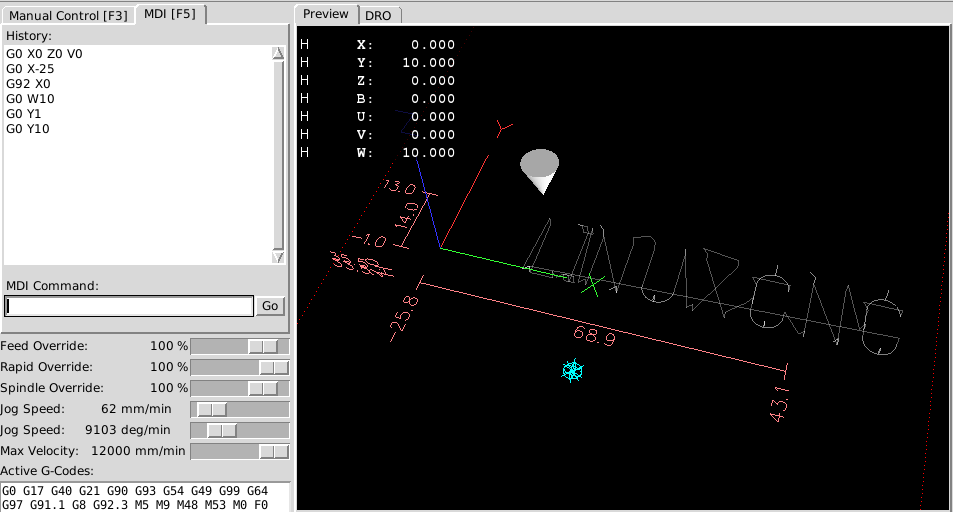
Backlash is partially mitigated by leadin instructions at a save z height in the direction of the next cut. Reapted tool entry will occur. The rotation axis goes with no hysteresis, that is particularly nice on this setup.
The x-axis of my machine shows substantial hysteresis if cutting under medium too high material loads. The gcode itself utilizes unidirectional positioning for any path segment and should no exhibit hysteresis upon low cutting loads.
Attachments:
Last edit: 19 Apr 2022 11:00 by Matt Hat.
Please Log in or Create an account to join the conversation.
- Matt Hat
- Offline
- Senior Member
-
Less
More
- Posts: 47
- Thank you received: 2
19 Apr 2022 10:19 - 22 Apr 2022 22:17 #240642
by Matt Hat
Replied by Matt Hat on topic How to warp XY instruction around a cylinder to e.g. engrave text on pens
And the gcode for engraving - for once - the example text LINUXCNC onto an cylindrical rod conserving length scales.
Prior to use: Homing joint7 will home your machine y-axis. Then call G92 Y0 (if not loaded a such) and use the v-axis to position your physical y-axis to have the rod axis at y=0. The surface cut starts at x=0 and z=0, which is at the top surface of the rod - touch-off the rod - an at the left lower anchor of the text. Then use:
G92 X0 Z0 V0 U0
Any G-command on the Y axis will do nothing as long <_rod-radius>:=W=0.
G0 W<_rod_radius>
Any G-command on the Y axis will now rotate your part (physical rotation about x-axis)
Off-axis movements can be simply done by use of axis u, which is now controlling the normal machine y-axis. XUZ behaves like the default trivkins configuration.
Last edit: 22 Apr 2022 22:17 by Matt Hat.
Please Log in or Create an account to join the conversation.
- Matt Hat
- Offline
- Senior Member
-
Less
More
- Posts: 47
- Thank you received: 2
19 Apr 2022 10:37 - 19 Apr 2022 11:03 #240643
by Matt Hat
Replied by Matt Hat on topic How to warp XY instruction around a cylinder to e.g. engrave text on pens
The result with my first selfmade low-cost desktop machine:
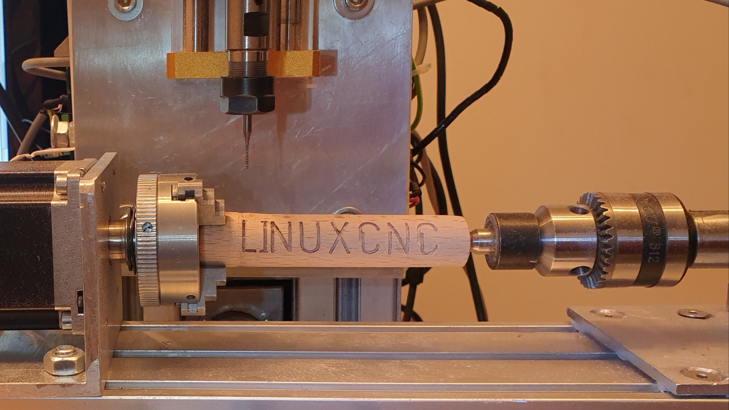
The letter C is cut with substantial hysteresis along x. For this low-cost machine with open loop control, the material load was simply too high. Cutting came with actual loss of motor steps during the curved parts of the C.
The letter C is cut with substantial hysteresis along x. For this low-cost machine with open loop control, the material load was simply too high. Cutting came with actual loss of motor steps during the curved parts of the C.
Attachments:
Last edit: 19 Apr 2022 11:03 by Matt Hat.
The following user(s) said Thank You: Clive S
Please Log in or Create an account to join the conversation.
- Matt Hat
- Offline
- Senior Member
-
Less
More
- Posts: 47
- Thank you received: 2
19 Apr 2022 11:41 - 19 Apr 2022 11:49 #240646
by Matt Hat
Replied by Matt Hat on topic How to warp XY instruction around a cylinder to e.g. engrave text on pens
I just realized that lath-like operations become now very simple. We can use any rectangular pocket macro to actually shape rods ")
We can e.g. keep the parameter W fix at the raw material diameter, or even use it to have degree units along Y, using e.g. W=10*180/pi=5.73 (Factor 10 is arbitrarily chosen). Then G0 Y36 will rotate the part just once.
A pockets of size X*rod_circumference*Z will convert to lath operation in XZ plane (vertical, not like typical horizontal xz). The rod_circumference is maximally the raw material circumference, when using W=rod_diameter. When using W=5.73 the width of the pocket should be set to something like 37 (corresponding to 370°, a little more than 365°).
We would obviously use a miller, and not a lath tool, and turn the part for each cylindrical surface only once per depth increment along z.
Last edit: 19 Apr 2022 11:49 by Matt Hat.
Please Log in or Create an account to join the conversation.
- tommylight
-

- Away
- Moderator
-
Less
More
- Posts: 21690
- Thank you received: 7412
19 Apr 2022 19:37 #240677
by tommylight
Replied by tommylight on topic How to warp XY instruction around a cylinder to e.g. engrave text on pens
I might be a little late to the party, but i do rotational axis as X, and make a new config for each diameter of material with the proper scaling for 1 rotation. This is for plasma cutters, makes it easy to use for new clients just by explaining to think of it as a paper sheet folded to a round, so they can design everything in 2D.
Last machine i built needed only 4 configs for 4 material diameters, configs named by diameter.
Last machine i built needed only 4 configs for 4 material diameters, configs named by diameter.
Please Log in or Create an account to join the conversation.
- Matt Hat
- Offline
- Senior Member
-
Less
More
- Posts: 47
- Thank you received: 2
19 Apr 2022 23:13 - 22 Apr 2022 22:06 #240702
by Matt Hat
Replied by Matt Hat on topic How to warp XY instruction around a cylinder to e.g. engrave text on pens
I agree - simple options first. Particularly if sheet metal is used to form bins, cans, tanks, etc. But then, why not cutting in the flat stock prior to shaping?
I am working right now on engraving periodic patterns, like zig zag lines going around a 'magic' stick. Hopefully soon with some results to show.
The original intension was to link the radius (W) directly to the z-coordinate, with z=0 at the rotation axis. Then it forms just a cylindrical coord sys.
Alltogether saves the need for various configs, maintains trivkins functionality without reloading, and adds some crossover to lath-like operations.
Last edit: 22 Apr 2022 22:06 by Matt Hat.
Please Log in or Create an account to join the conversation.
- Matt Hat
- Offline
- Senior Member
-
Less
More
- Posts: 47
- Thank you received: 2
22 Apr 2022 21:40 - 22 Apr 2022 22:09 #240919
by Matt Hat
Replied by Matt Hat on topic How to warp XY instruction around a cylinder to e.g. engrave text on pens
I have cleaned up the kinematics file, the ini config, and the machine with some axis being stuck.
- Now u,v,w are again free to be used as normal tool offsets.
- Machine Y is mapped on B axis.- A axis is rotation as normal.- The cylinder radius is stored in axis C.
- Machine Y is moved prior to call gcode, using joint4. When cylinder axis lines up with the cutter, G92 B0 will do the job.
- A is used like a tool offset, applied to rotate the part to starting point, like using X. Then G92 X0 A0 Z0 sets the part origin.
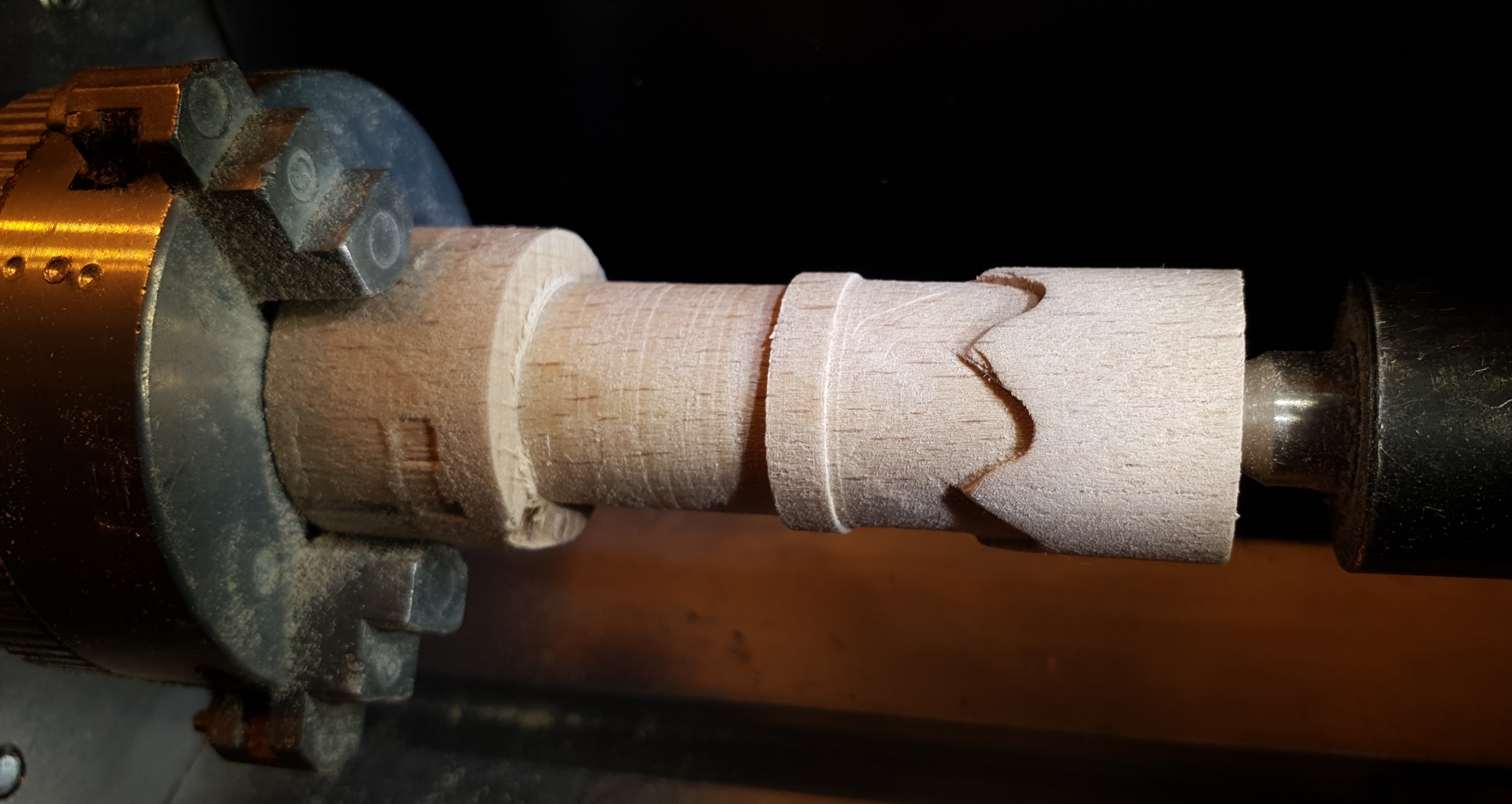
All together simple enough to remember in front of the machine. Attached a sample ngc that will cut some periodic zig zag pattern. My machine is far from high-end, but code is running fine. Hopefully I can cut some nice chess figures from hard wood.
- Now u,v,w are again free to be used as normal tool offsets.
- Machine Y is mapped on B axis.- A axis is rotation as normal.- The cylinder radius is stored in axis C.
- Machine Y is moved prior to call gcode, using joint4. When cylinder axis lines up with the cutter, G92 B0 will do the job.
- A is used like a tool offset, applied to rotate the part to starting point, like using X. Then G92 X0 A0 Z0 sets the part origin.
All together simple enough to remember in front of the machine. Attached a sample ngc that will cut some periodic zig zag pattern. My machine is far from high-end, but code is running fine. Hopefully I can cut some nice chess figures from hard wood.
Last edit: 22 Apr 2022 22:09 by Matt Hat.
Please Log in or Create an account to join the conversation.
- Matt Hat
- Offline
- Senior Member
-
Less
More
- Posts: 47
- Thank you received: 2
22 Apr 2022 22:04 #240924
by Matt Hat
Replied by Matt Hat on topic How to warp XY instruction around a cylinder to e.g. engrave text on pens
Attachments:
Please Log in or Create an account to join the conversation.
- Configuring LinuxCNC
- Advanced Configuration
- How to warp XY instruction around a cylinder to e.g. engrave text on pens
Time to create page: 0.441 seconds