Bridgeport Interact Refit
- csbrady
- Offline
- Senior Member
-

Less
More
- Posts: 72
- Thank you received: 10
21 Sep 2015 09:37 #62828
by csbrady
Bridgeport Interact Refit was created by csbrady
I decided to take the plunge and refit my mill with a linuxCNC controller. I am new to the world of machine control but have good electronics and Linux background. I will be replacing a Heidenhain TNC 151A. I have many questions but at this point I am looking for a sanity check for my general plan.
I am planning to use Mesa 5i25/7i77 boards. To simplify the process I plan to retain the existing, servos, motors and encoders (all working). I also plan leave the ladder logic implemented with a collection of relays in place replacing only the TNC controller. I will put the new controller in the pendant where the TNC now resides to simplify wiring. I plan to keep the original start,stop, Estop buttons, handwheel and jog controls. I plan to add potentiometers for the feed and spindle override.
My encoders are ERO 115's that have 11um sine wave outputs. I am planning to use EXE 602 interpolation boxes to convert the signals to digital.
For the user interface I am planning to use a 15" touch screen and hopefully I will not need a mouse or keyboard. However, I am not sure if everything can be done with a touch screen.
Is my plan sound? What am I missing? Are there surprises waiting for me? I don't know what I don't know.
Comments and suggestions would be appreciated.
Please Log in or Create an account to join the conversation.
- cncbasher
- Offline
- Moderator
-

Less
More
- Posts: 1021
- Thank you received: 202
21 Sep 2015 16:05 #62830
by cncbasher
Replied by cncbasher on topic Bridgeport Interact Refit
overall , thats exactly the way i would do it . speak with mesa they have a resolver card , you may find a better option is the 5i20 with servo and resolver addon's
it's been a while since i did a bridgeport , and thats what i used at that time , but that was before the 5i25 , you may find the 6 and 8 series fit too
if you go to JT'S web site he has all the files implemented for a bridgeport
gnipsel.com/shop/machine-shop.xhtml
if anything it's the resolvers that will give you the most trauma , so make sure you know what the connections are before you strip the old controller
The following user(s) said Thank You: csbrady
Please Log in or Create an account to join the conversation.
- andypugh
-

- Offline
- Moderator
-

Less
More
- Posts: 19715
- Thank you received: 4570
21 Sep 2015 22:24 #62834
by andypugh
Replied by andypugh on topic Bridgeport Interact Refit
There is a software PLC included in LinuxCNC, you can use that for your Ladder logic.
www.linuxcnc.org/docs/html/ladder/ladder-intro.html
www.linuxcnc.org/docs/html/ladder/classic-ladder.html
www.linuxcnc.org/docs/html/ladder/ladder-examples.html
I don't think that the Mesa Resolver card suggested by cncbasher is appropriate for the Heidenhain scales (which is for resolvers rather than sinusoudal output encoders) , but an alternative to the EXE boxes is a development board from ICHaus.
With the ICHaus board there is the option of switching to digital SPI position feedback, rather than converting to quadrature. (Not that I know of anyone who has actually one this, but all the components exist)
The following user(s) said Thank You: csbrady
Please Log in or Create an account to join the conversation.
- cncbasher
- Offline
- Moderator
-

Less
More
- Posts: 1021
- Thank you received: 202
22 Sep 2015 01:45 #62839
by cncbasher
Replied by cncbasher on topic Bridgeport Interact Refit
thanks Andy i was missing that particular option , good catch
The following user(s) said Thank You: csbrady
Please Log in or Create an account to join the conversation.
- csbrady
- Offline
- Senior Member
-

Less
More
- Posts: 72
- Thank you received: 10
17 Jan 2016 03:33 - 17 Jan 2016 03:59 #68558
by csbrady
Replied by csbrady on topic Bridgeport Interact Refit
I just wrapped up my retrofit project and I am very happy with the results. It was a challenging but very interesting project. I will be posting pictures and details over the next few days. Hopefully, it will be helpful to others. I should have posted this as I went along, but better late than never.
Installment #1 - The computer
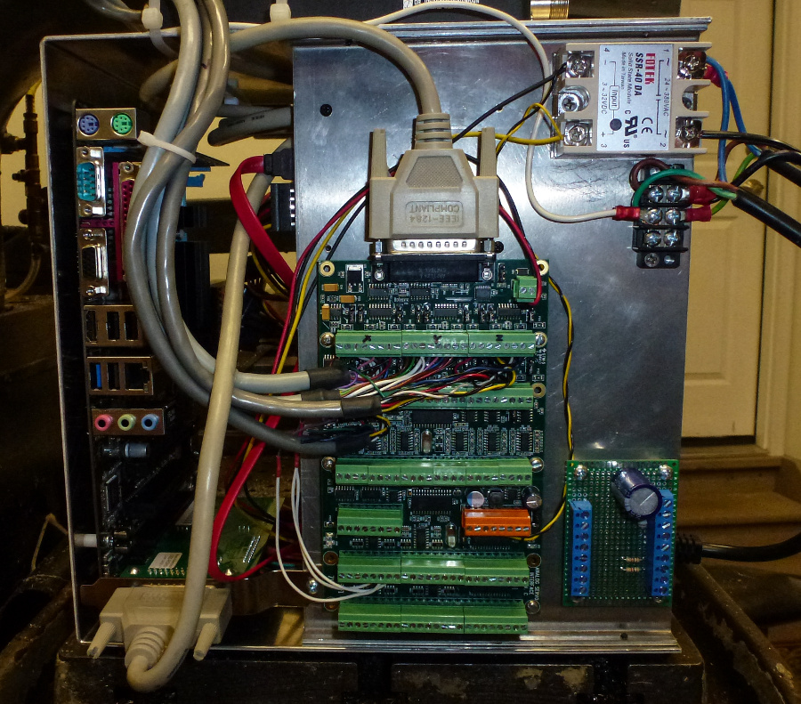
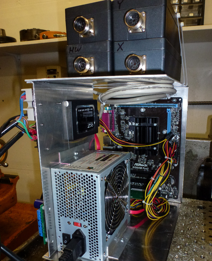
For the motherboard I selected an ASROCK Q1900M PRO3. It is inexpensive with a quad core 2.0 GHz 10 watt fan less CPU. Plenty of horsepower to RUN LinuxCNC and the fanless part is important for reliability, CPU cooler fans are notoriously unreliable. I also wanted low power so that it would not overheat in the un-vented pendant. With 2 cores disabled via the ioslcpus parameter the jitter was less than 5000ns. I added a 60GB SATA SSD, 2 GB of memory and a 350w power supply. 350 watts is overkill but I wanted to stay with a standard form factor to make replacement easy.
I selected the Mesa 5i25 + 7i77 boards for the IO. To mount everything I had a simple chassis made from .080 Aluminum that would fit into the original pendant.
Last edit: 17 Jan 2016 03:59 by csbrady.
Please Log in or Create an account to join the conversation.
- csbrady
- Offline
- Senior Member
-

Less
More
- Posts: 72
- Thank you received: 10
17 Jan 2016 03:58 - 25 Jan 2016 04:26 #68561
by csbrady
Replied by csbrady on topic Bridgeport Interact Refit
Installment #2 - Controls and Touch screen GUI
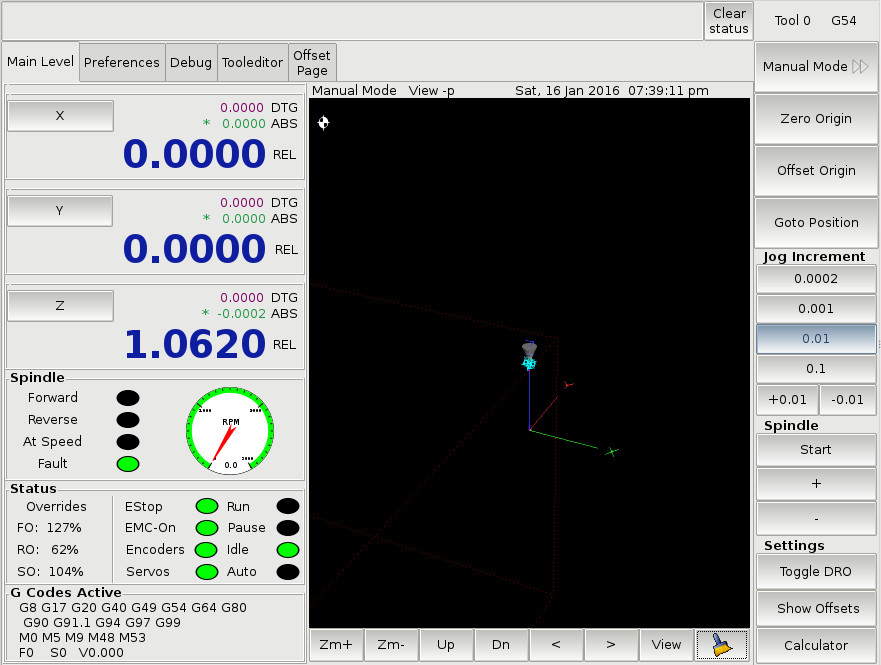
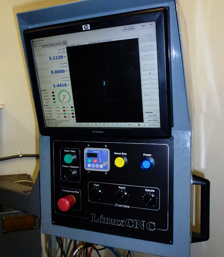
Early in the process I decided that I wanted to use a touch screen. But I was uncertain if it was realistic to operate LinuxCNC with no keyboard. I also found that the existing touch screen capable GUIs were not quite what I was looking for. I liked Gscreen the best, but there were lots of buttons and functions that I didn't want or need. So I decided to take on the task of creating a customized variant of Gsrceen that only had the functions I wanted. I also wanted to not have any nesting of buttons. So in each mode, all of the buttons for that mode need to be visible all of the time. I also decided to use physical controls for all of the operational functions (start, stop, overrides, etc.)I am a capable programmer, but this ended up being a far more difficult tasks than I had anticipated.
I find that the touch screen is very easy to use and it is rare that a keyboard is needed. I bought a Logitech K400 that I keep in a drawer. It's perfect for those rare times that a keyboard is needed.
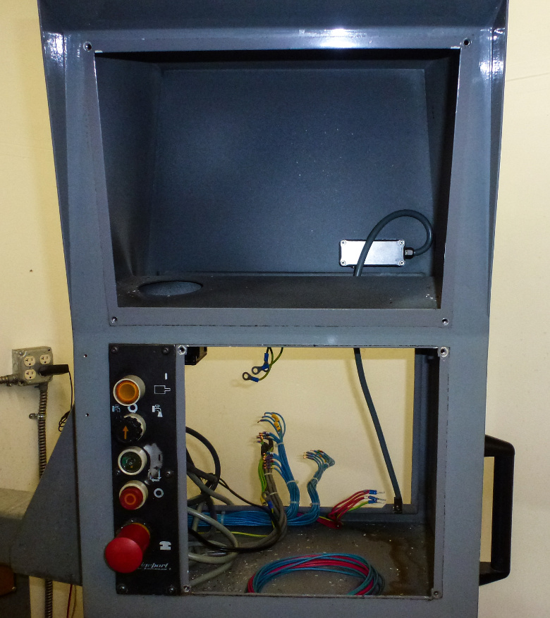
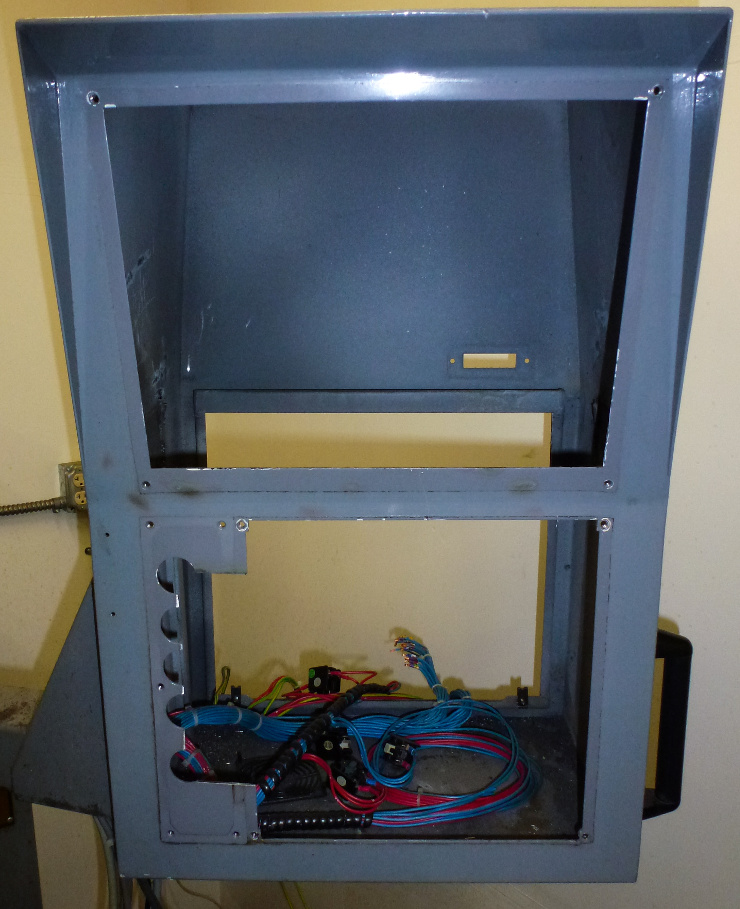
I purchased a used 15" touchscreen on ebay for $80. It is mounted in the pendant where the old monitor was. I made a nice, replacement control panel for the new set of buttons. The only button I used from the original panel was the Estop since the others were worn.
Last edit: 25 Jan 2016 04:26 by csbrady.
Please Log in or Create an account to join the conversation.
- cmorley
- Away
- Moderator
-

Less
More
- Posts: 7239
- Thank you received: 2107
17 Jan 2016 06:35 #68573
by cmorley
Replied by cmorley on topic Bridgeport Interact Refit
Nice job on the retrofit.
Would you be interested in donating your GUI code to linuxcnc, if possible?
Chris M
Would you be interested in donating your GUI code to linuxcnc, if possible?
Chris M
Please Log in or Create an account to join the conversation.
- andypugh
-

- Offline
- Moderator
-

Less
More
- Posts: 19715
- Thank you received: 4570
17 Jan 2016 10:39 #68579
by andypugh
I have one of these in a little "holster" on the side of my control panel:
www.amazon.co.uk/gp/product/B004TQL3YS?qid=1453027099
It does the trick when I want to edit a bit of G-code or similar.
Replied by andypugh on topic Bridgeport Interact Refit
I find that the touch screen is very easy to use and it is rare that a keyboard is needed. I bought a Logitech K400 that I keep in a drawer. It's perfect for those rare times that a keyboard is needed.
I have one of these in a little "holster" on the side of my control panel:
www.amazon.co.uk/gp/product/B004TQL3YS?qid=1453027099
It does the trick when I want to edit a bit of G-code or similar.
Please Log in or Create an account to join the conversation.
- csbrady
- Offline
- Senior Member
-

Less
More
- Posts: 72
- Thank you received: 10
17 Jan 2016 15:22 #68589
by csbrady
Replied by csbrady on topic Bridgeport Interact Refit
Chris, yes I would be interested in contributing the GUI. There are a couple minor quirks that need to get fixed plus I want to shake it out a little longer before releasing it. Please let me know what the process is.
Please Log in or Create an account to join the conversation.
- csbrady
- Offline
- Senior Member
-

Less
More
- Posts: 72
- Thank you received: 10
25 Jan 2016 04:24 #69077
by csbrady
Replied by csbrady on topic Bridgeport Interact Refit
Installment #3 - Spindle integration
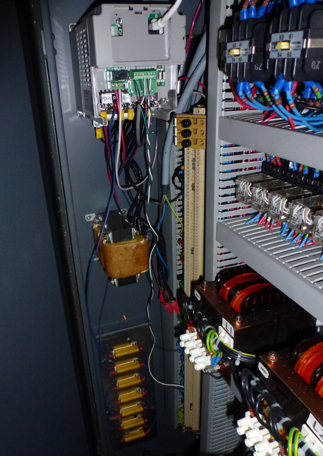
Some time ago I installed a Hitachi SJ200 VFD for the spindle. This was primarily so that the mill could be operated with single phase power. With the new controller I was able to better integrate the VFD. I connected signals to stop the spindle on an estop, reset the VFD after an estop and trigger an estop if there is a VFD fault. Of course the start/stop and speed are also controlled. This was all fairly simple to do using input/output pins on the VFD. I could have used the RS422 interface but could not find an up do date driver for the SJ200. Wiring directly was simpler, did everything I wanted and was easy to troubleshoot.
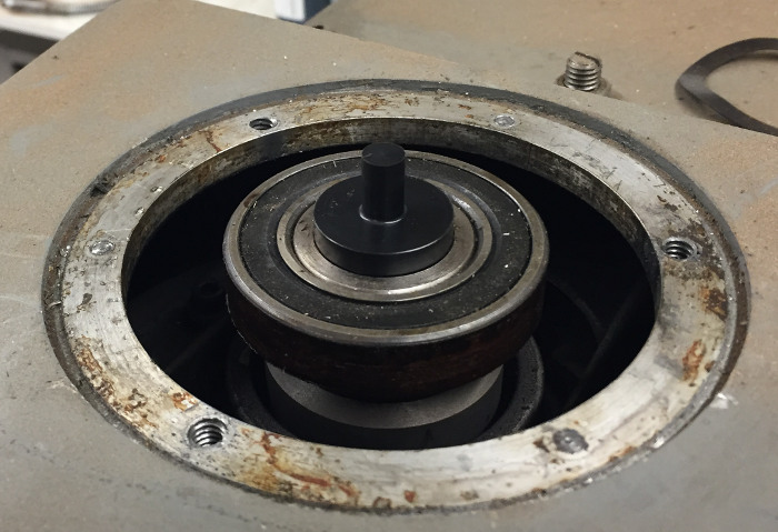
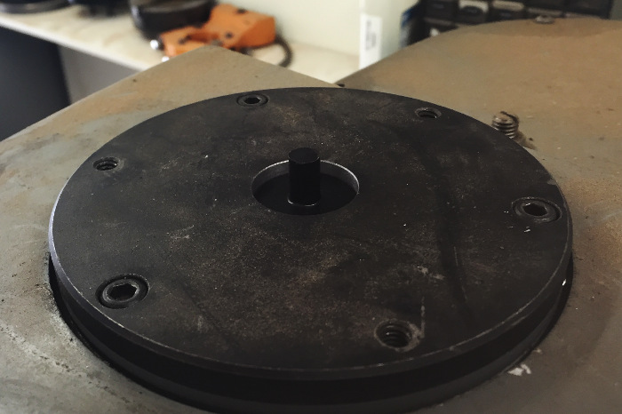
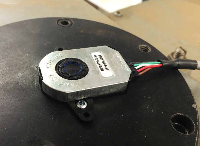
I also installed an AMT10 encoder on the spindle so that I can do rigid tapping. This required making a adapter to go into the top of the spindle as shown below. I made it out of Delrin since it's what I had on hand.
I needed to open the hole in the top bearing plate a little to clear the adapter.
The VFD was unable to do braking without an external braking resistor. I constructed a 42 ohm 350 watt braking resister assembly by mounting 7, 6 ohm, 50 watt on a piece of 1/8" aluminum. The resistors are wired in series.
I did some rigid tapping with this setup and it actually worked! The braking rate is somewhat limited with the VFD so the tapping RPM needs to be less than 600 to avoid tripping the VFD. I don't think I would ever want to tap faster than that so it's not a problem.
Please Log in or Create an account to join the conversation.
Moderators: piasdom
Time to create page: 0.332 seconds

