deckel fp4ma retrofit
- bahrabadi
-
 Topic Author
- Offline
- Junior Member
-

Less
More
- Posts: 21
- Thank you received: 0
10 Dec 2016 14:15 #83881
by bahrabadi
deckel fp4ma retrofit was created by bahrabadi
Please Log in or Create an account to join the conversation.
- andypugh
-

- Offline
- Moderator
-

Less
More
- Posts: 19767
- Thank you received: 4589
10 Dec 2016 16:46 #83882
by andypugh
Replied by andypugh on topic deckel fp4ma retrofit
It is almost certainly +/-10V control and so relatively easy to control with LinuxCNC.
I have some wiring diagrams from another owner, but they are too big to attach here. I will email them separately.
I have some wiring diagrams from another owner, but they are too big to attach here. I will email them separately.
The following user(s) said Thank You: bahrabadi
Please Log in or Create an account to join the conversation.
- bahrabadi
-
 Topic Author
- Offline
- Junior Member
-

Less
More
- Posts: 21
- Thank you received: 0
10 Dec 2016 16:52 - 10 Dec 2016 18:55 #83883
by bahrabadi
Replied by bahrabadi on topic deckel fp4ma retrofit
thats great.how about servo encoders.are they quadrate or resolver ?and what kind of boards show i use?5i25 And 7i77 are good for this porpuse?
Last edit: 10 Dec 2016 18:55 by bahrabadi.
Please Log in or Create an account to join the conversation.
- tommylight
-

- Away
- Moderator
-

Less
More
- Posts: 21145
- Thank you received: 7221
11 Dec 2016 01:25 #83894
by tommylight
Replied by tommylight on topic deckel fp4ma retrofit
Take some pictures of motors and attached encoder/tacho/resolver, but it most probably uses encoders and tachos simultaneously. That would be easily controlled by a mesa 5i25/6i25/ with 7i77. Do you have the 3 axis or 4 axis with rotating table version?
I was looking to buy one with 3 axis a while back, but i found a better deal here for a much bigger 4 axis mill with ATC, i have to wait and see how this goes.
I was looking to buy one with 3 axis a while back, but i found a better deal here for a much bigger 4 axis mill with ATC, i have to wait and see how this goes.
Please Log in or Create an account to join the conversation.
- bahrabadi
-
 Topic Author
- Offline
- Junior Member
-

Less
More
- Posts: 21
- Thank you received: 0
12 Dec 2016 07:11 - 12 Dec 2016 07:14 #83936
by bahrabadi
Replied by bahrabadi on topic deckel fp4ma retrofit
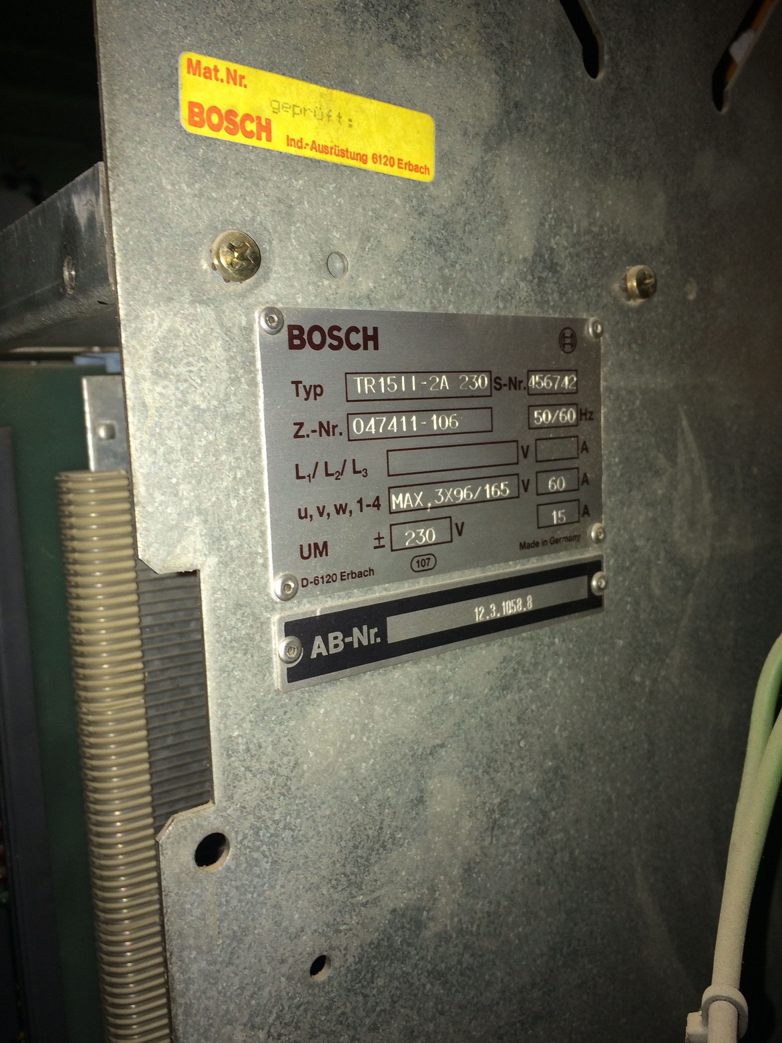
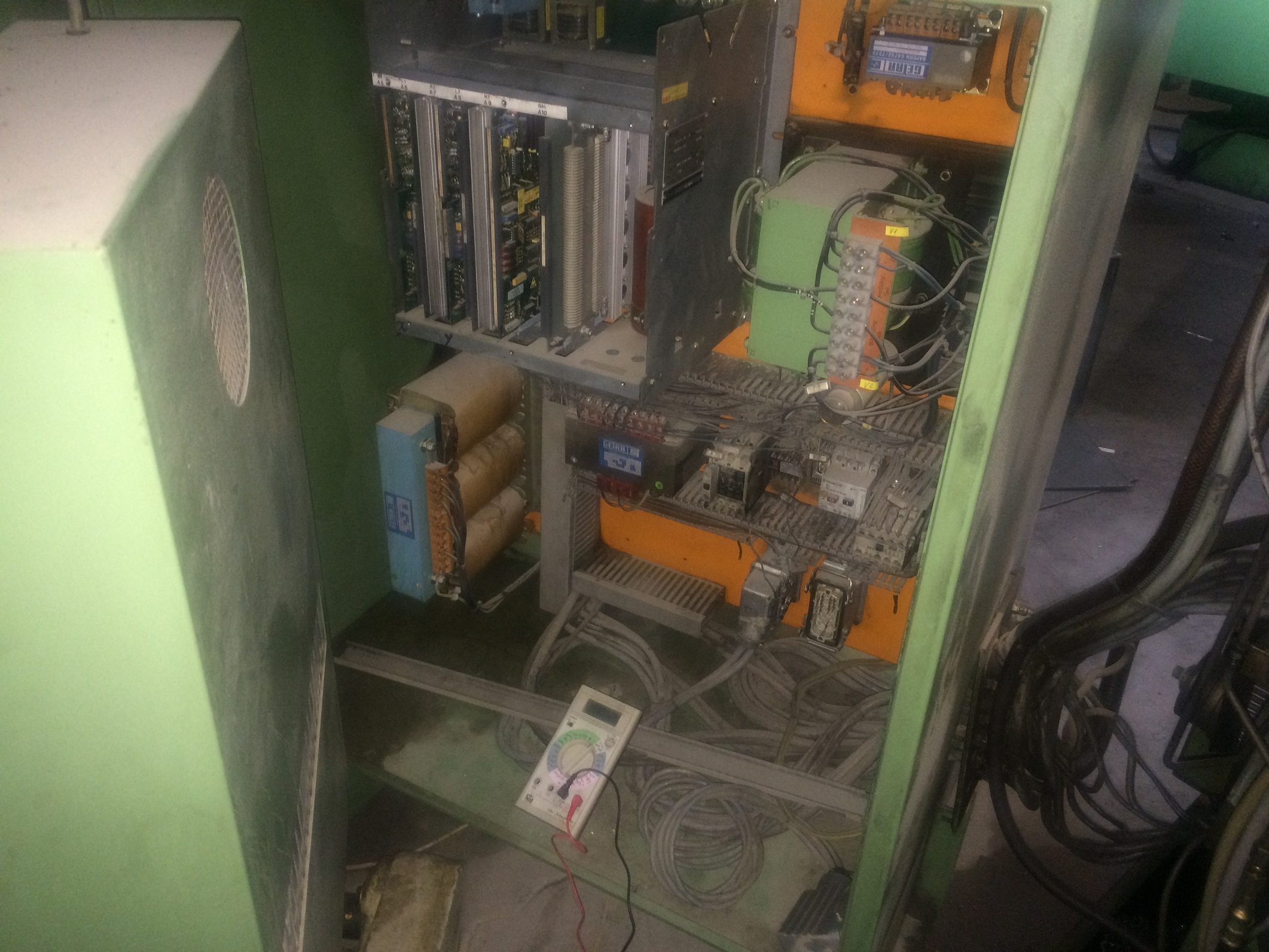
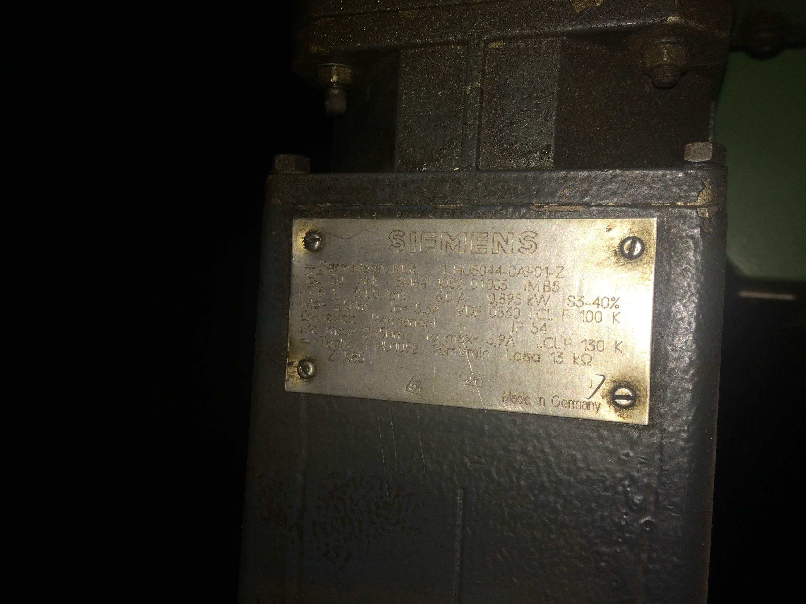
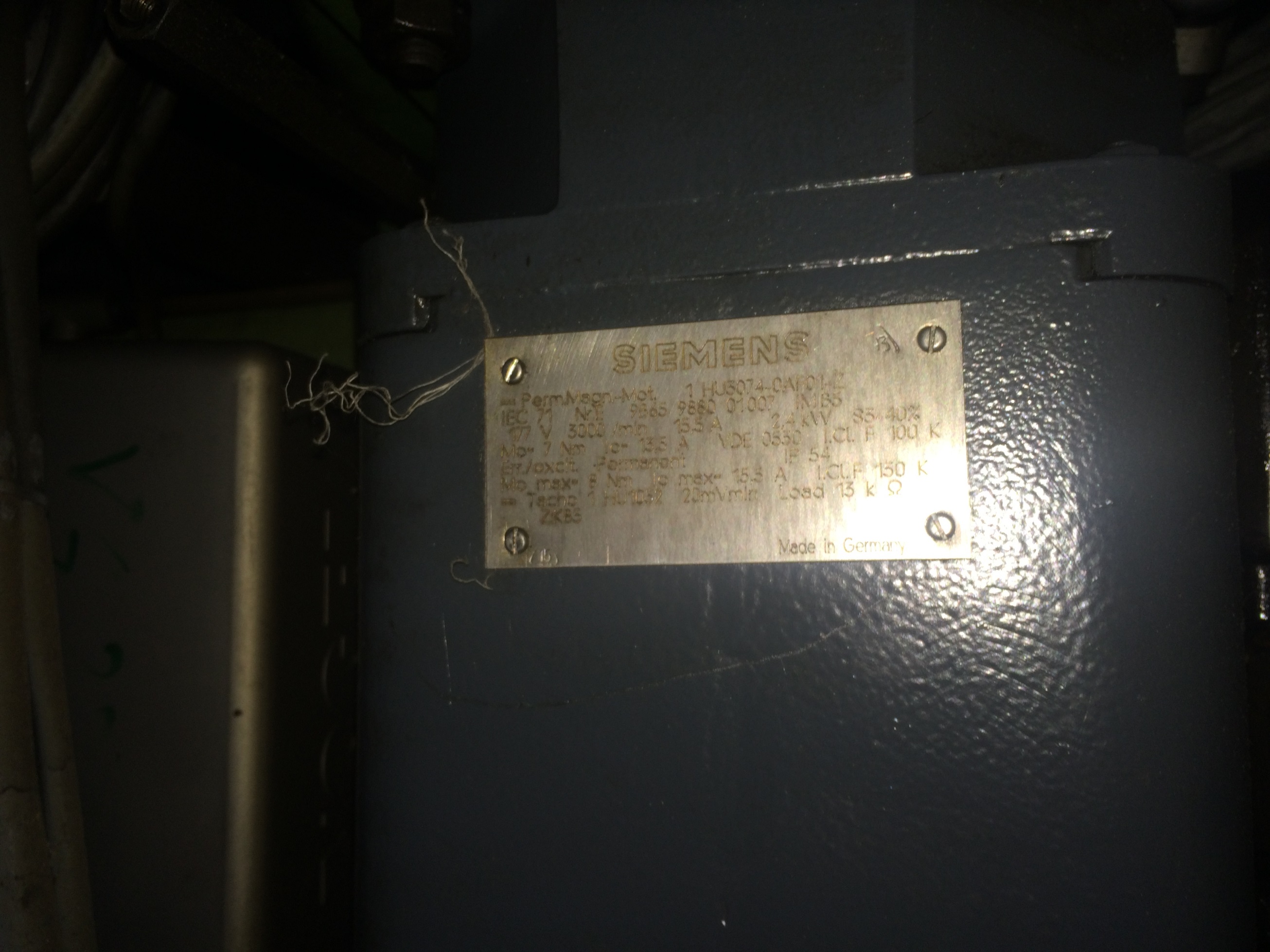
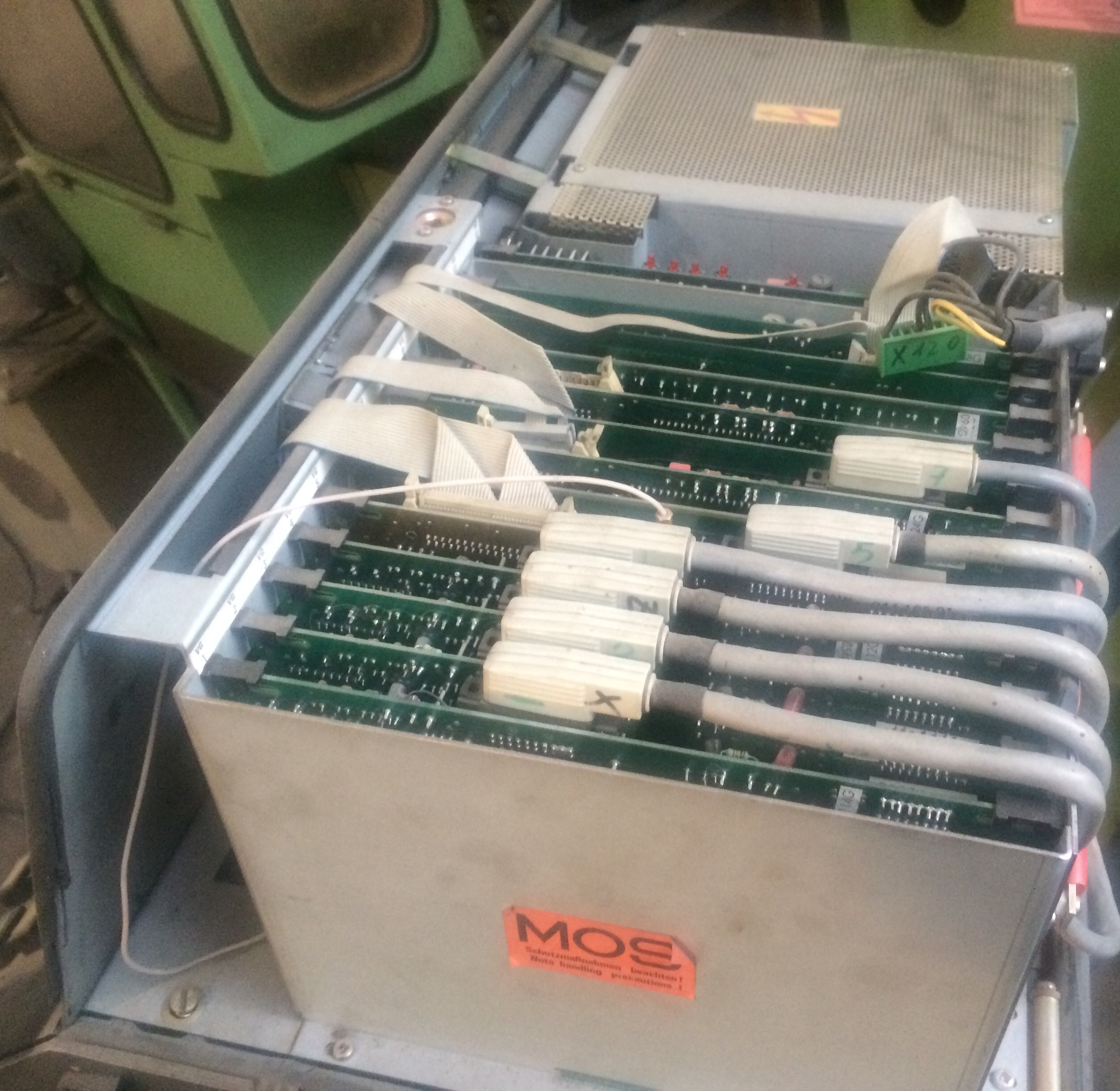
these are the photos of x and z axis motors.I have the three axis version.by the way the four red leds of driver light up when i power on the machine.can it be fixed? I should mention one of the contactors of machine that is on other side of machine is damaged.I only ask this becuase I don't want to sped money for the boards and later find out that the dirves are damaged too.
thanks in advance
p.s sorry for my bad english.It is my second language after all:)
thanks in advance
p.s sorry for my bad english.It is my second language after all:)
Last edit: 12 Dec 2016 07:14 by bahrabadi. Reason: wrong pics
Please Log in or Create an account to join the conversation.
- andypugh
-

- Offline
- Moderator
-

Less
More
- Posts: 19767
- Thank you received: 4589
12 Dec 2016 09:55 #83938
by andypugh
Replied by andypugh on topic deckel fp4ma retrofit
The wiring diagrams I have show DC brushed servos and Tachometers
(See the attached extract).
Can you confirm if that seems likely in your case? You would expect to see only two power wires to the motors, and signs of brushes and two smaller wires for the tachometer. There may also be 3 or 6 encoder wires, though the machine might be position-controlled from scales on the slides.
There are many interlocks in the system. The red lights on the drives could be any number of things, including the doors being open.
Please Log in or Create an account to join the conversation.
- tommylight
-

- Away
- Moderator
-

Less
More
- Posts: 21145
- Thank you received: 7221
12 Dec 2016 12:33 #83945
by tommylight
Replied by tommylight on topic deckel fp4ma retrofit
There are tachos on both of them, 2V/krpm. i can not see any reference to encoders on the plate, and the pictures do not show the complete motors. Maybe a search for motor models can reveal more.
Please Log in or Create an account to join the conversation.
- ROG
- Offline
- New Member
-

Less
More
- Posts: 8
- Thank you received: 1
12 Dec 2016 14:59 #83948
by ROG
Replied by ROG on topic deckel fp4ma retrofit
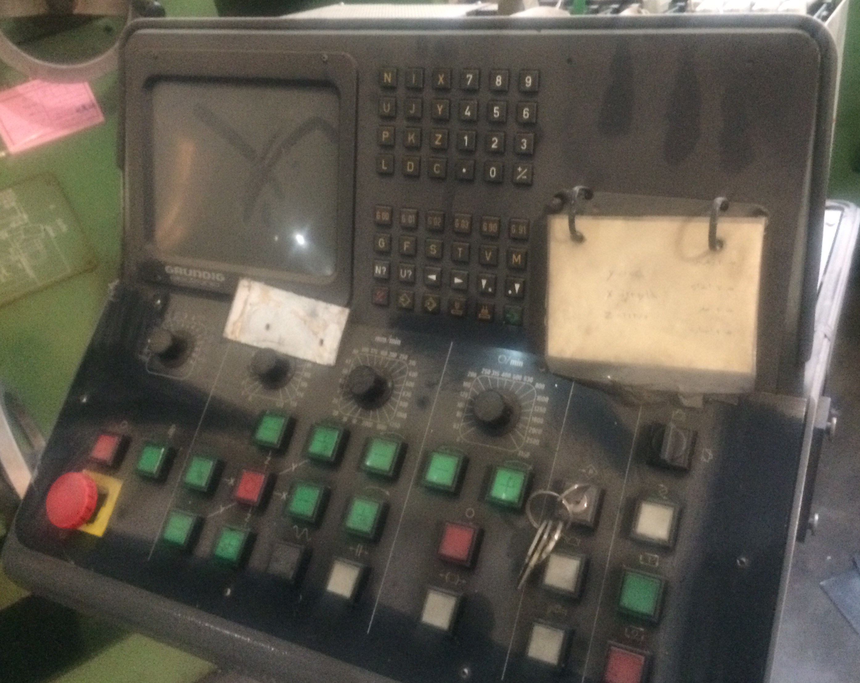
What control does / did the machine have?
Is the control broken? ... what functionality do you have?
It's likely to be either a Heidenhain TNC 300 series or a Grundig Dialog 11.
I know nothing about the Grundig control.
I have an FP2 with a Heidenhain TNC 315. You should have Heidenhain glass scale linear encoders on all the axis. There are no encoders on the motors or ball screws.
The encoders will likely have an 11ua sinusoidal output and a 20 micron grating pitch. Definitely if it's a Heidenhain control, very likely if its Grundig.
The TNC would read and interpolate these directly. The MESA 7i77 wont so you will need to put interpolators between the encoders and the 7i77.
There are plenty on EBay and they range from 5 fold interpolation and 400 fold interpolation.
A 5 fold interpolator will convert your 20 (micron) / 5 (interpolation) /4 (quadrature) giving you in theory 1 micron positioning accuracy.
www.ebay.co.uk/itm/Heidenhain-EXE-602-D-...d:g:FugAAOSwjXRXa-bd
You will need to check the spec properly, that was just an example.
www.heidenhain.com/en_US/products/subseq...nics/exe-600-series/
There should be several M23 plugs in the back of the cabinet coming from the encoders. these need to be plugged into the exe units and then a cable made up from the EXE to the 7i77
They will probably be labelled X1,X2 and X3 .... X Y and Z encoders accordingly.
The bosch control will be expecting a +/-10V signal so the inputs to the drive can be wired straight to the 7i77. There will also be one or more enable signals and possibly a "drive ok" signal back to the control.
I would leave everything on the output side of the drive, motors, tachos ... cables .... everything well alone. Don't touch the pots on the cards that are in the drive.
You should be able to test the movement of the axis by applying a small voltage to the drive inputs ...0.5 ... 1V for example, and make sure the axis move. Once you have managed to get the drive enabled that is.
if you can get the axis moving, then try wiring the encoders to the 7i77 and monitor the position signals in HAL monitor or HALscope.
Once you know you are reading the encoder signals ok and have made sure that the axis are moving in the correct directions, then start off with very low PID settings and start to tune the PID in Linux CNC. I can't remember what the pots do, but my advice would be only to twiddle with them if you can't get good following error by tuning in LinuxCNC.
Apart from possible new brushes in the motors, if all is as it should be, you shouldn't need to worry about the motors or the drive.
On the LV side of the drive, there will be 3 "pairs" for the 3 axis control signals which should be pretty obvious. Identify these and then see what else is left and try to work out by a process of elimination what s what. One will be 0v and one will be a 24V supply for example. you should be able to find these by continuity test to the 0v and 24V supply.
Leave all the motors as they are and try to get the drive up, move the axis manually by applying a small input voltage and see what's working and what's not. Unless the drive is shagged, once enabled there should be too much to worry about, but that's the starting point.
Please Log in or Create an account to join the conversation.
- ROG
- Offline
- New Member
-

Less
More
- Posts: 8
- Thank you received: 1
12 Dec 2016 15:22 #83949
by ROG
Replied by ROG on topic deckel fp4ma retrofit
As Andy points out, the drive will not "enable" unless it sees the relevant signals from the control.
The LEDs on my drive are all red until I press the "NC ON" button and the control is happy with everything and then it will enable the drive. Assuming that you have a defective control, and that's the reason for the retrofit, you will never get the the drive to enable just by powering everything up. ... Hence the red LEDs
The LEDs on my drive are all red until I press the "NC ON" button and the control is happy with everything and then it will enable the drive. Assuming that you have a defective control, and that's the reason for the retrofit, you will never get the the drive to enable just by powering everything up. ... Hence the red LEDs
Please Log in or Create an account to join the conversation.
- bahrabadi
-
 Topic Author
- Offline
- Junior Member
-

Less
More
- Posts: 21
- Thank you received: 0
12 Dec 2016 17:57 #83957
by bahrabadi
Replied by bahrabadi on topic deckel fp4ma retrofit
Please Log in or Create an account to join the conversation.
Moderators: piasdom
Time to create page: 0.476 seconds

