Retrofitting a 1986 Maho MH400E
- RotarySMP
-
 Topic Author
- Offline
- Platinum Member
-

- Posts: 1627
- Thank you received: 595
Here is a summary of this project...
Hi All,
I'm an aircraft maintenance engineer living in Vienna. I purchased a 1986 MAHO MH400E which came out of a school (HWK Passau).
It is in excellent mechanical condition, but currently not functioning. The seller powered it up, but only the monitor came up with snow, with no input signal. The Phillips didn't appear to power up. The Hydraulic start button did nothing.
Before I power it up again and start troubleshooting the existing control system to get it running, I have ordered new electrolytic capacitors for the Indramat 3TRM2 DC drives and for the Phillips 432/10 PSU module.
Since this early model 432/10 with 8088 CPU only supports 2.5D milling, I am also starting to plan a retrofit with LinuxCNC and MESA 5i25 / 7i77 / 7ixx cards. I have the original wiring diagram and am working through system by system, figuring out how to interface the existing Indramat drives, the existing Heidenhain EXE card, and the MAHO 28A1 relay board on the door. I have a little experience with LinuxCNC on stepper based minilathe conversion. This is a whole other level of project.
I'm planning on using Gmoccapy on a touch screen, but would like to add physical buttons around the lower and RH sides for the soft keys, sort of like a modern Heidenhain controller.
My questions:
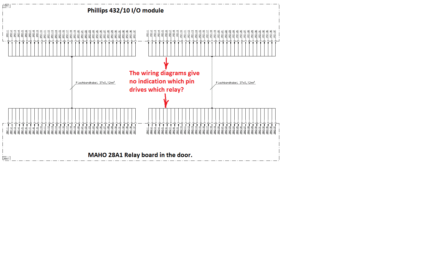
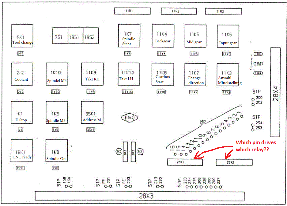
1/ For those who have done a MAHO retrofit, how many MESA I/O daughter cards are necessary? This a basic machine with no tool changer or pallet, but the 18 speed gearbox will need a fair bit of I/O. I can see that the 16 output pins of the 7i77 will not suffice, to interface with the MAHO relay board in the door (28A1). The Maho board has two 37 pin ribbon connections, 28X1 is the boards input, while 28X2 is the output. There are only 17 relays, so there can't be 36 Inputs/outputs on each ribbon cable. I am wondering if I could use a 7i69 ? There are at least two functions on that relay board which will no long be active (the Set Constants switch and system test)
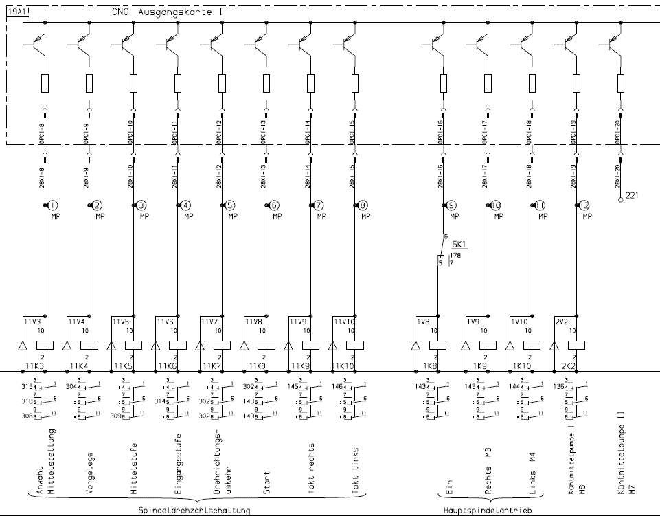
2/ The wiring diagrams are clear for the electrical interconnects, except for the two ribbon cables which connect the CNC controller to the relay board at 28X1 and 28X2. These just give the pin numbers at both ends, but give no information about which relay is controlled from which pin.
3/ I have a specific request to Anders (ABK1212). In PM you posted an excel file with the function of each component. Could I please have a copy of that, as the link in PM Is dead?
4/ The Maho MH400E has the 18 speed gearbox, with 10 relays controlling the shifters through three motors, and feedback from 10 switches. In addition there are CW and CCW twitch relays to bump the main spindle motor during gearchange. I have read of a number of cases of people controlling this under LinuxCNC, but have only seen fragments of the solution such as Müllernick's videos, AndyP's generic gearbox control HAL code here, etc.
forum.linuxcnc.org/38-general-linuxcnc-q...ntrol?start=10#81876
For LinuxCNC is it better to control this system in ClassicLadder, or write a software widget for it? I did a Python course this year, so it would be an interesting project, but am a little lost as to how to approach it. Any assistance of how to do this would be appreciated.
5/ Is it best to integrate the soft key buttons through MESA Interface pins, or is there a more elegant solution than one input pin per button?
Thanks for your interest,
Mark
Please Log in or Create an account to join the conversation.
- andypugh
-

- Offline
- Moderator
-

- Posts: 19854
- Thank you received: 4635
There are only 17 relays, so there can't be 36 Inputs/outputs on each ribbon cable. I am wondering if I could use a 7i69 ?
The 7i69 is a 5V output card without very much current-drive capacity. (5V / 15mA sink capacity) so I don't think that it would have the drive capacity for mechanical relays (it would work well with solid-state relays, though). The 7i64 and 7i66 can drive 2.5A loads (which is probably more than you need) but they cost rather more. The 7i84 might be what you want, that can drive 24V loads at 300mA.
store.mesanet.com/index.php?route=product/category&path=83_88
4/ The Maho MH400E has the 18 speed gearbox, with 10 relays controlling the shifters through three motors,
...
is it better to control this system in ClassicLadder, or write a software widget for it? I did a Python course this year,
A Python HAL component would be one way, certainly, though it would not run in the realtime layer (realtime HAL components need to be written in C). This probably isn't a huge problem, the popular modbus VFD drivers don't run in realtime either
Please Log in or Create an account to join the conversation.
- RotarySMP
-
Topic Author
- Offline
- Platinum Member
-
- Posts: 1627
- Thank you received: 595
Thanks for pointing that out. I was hoping to use the 7i69 because the ribbon cables could have been easily spliced into the 50 pin connectors of that board, but that is off the table. I guess the decision between the 7i64 and 7i84 will be decided by whether I need more than the 32 outputs of the 7i77 plus 7i84 together.
I sure hope someone has an answer to my question #2, as I have so far not being able to source a Phillips 432 user manual, which I would hope would list the function each output and input pin.
I have looked at your C Hal component, but know nothing about C programming, so the syntax is a bit spanish to me. I'm not sure what is place holder for machine specific code o be added, and what is final code. This is just the HAL interface, right? The actual switching logic which commands those HAL pins would be done in the ladder wouldn't it?
Mark
Please Log in or Create an account to join the conversation.
- andypugh
-
- Offline
- Moderator
-
- Posts: 19854
- Thank you received: 4635
I am not saying that the 6i69 is definitely wrong, just that you need to look at what the drive voltage and current is that is needed at the other end. If the existing relays are controlled by a ribbon cable then perhaps there is some buffering on the other end, or the relays really are low-power (you don't often see ribbon cable used for anything other than logic-level signalling)Thanks for pointing that out. I was hoping to use the 7i69 because the ribbon cables could have been easily spliced into the 50 pin connectors of that board, but that is off the table. I guess the decision between the 7i64 and 7i84 will be decided by whether I need more than the 32 outputs of the 7i77 plus 7i84 together.
I sure hope someone has an answer to my question #2, as I have so far not being able to source a Phillips 432 user manual, which I would hope would list the function each output and input pin.
There is an electrical schematic here, (near the bottom of the page) and other manuals too is it the right one?
www.smoregrava.net/Maho/mahomh500.htm
Please Log in or Create an account to join the conversation.
- RotarySMP
-
Topic Author
- Offline
- Platinum Member
-
- Posts: 1627
- Thank you received: 595
I am not saying that the 7i69 is definitely wrong, just that you need to look at what the drive voltage and current is that is needed at the other end. If the existing relays are controlled by a ribbon cable then perhaps there is some buffering on the other end, or the relays really are low-power (you don't often see ribbon cable used for anything other than logic-level signalling)
I checked and the shrack relays installed on the MAHO 28A1 relay board have 24V coils, so your first instinct was correct. Saved me heading down a dead end. Thanks
cncbote.de/artikel/maho-relais-platine-28a1-27-69-923/
There is an electrical schematic here, (near the bottom of the page) and other manuals too is it the right one?
www.smoregrava.net/Maho/mahomh500.htm
Thanks for that reminder. I knew that site, and took another detailed look at his schematics. Lead me to comparing differences with my machines schematics. Turns out I had a brain fade. The schematics do spell out exacting which signal is on which pin of those ribbon cables.
That information is scattered across multiple sheets, but it is all there. That means I can now start mapping I/O to a 7i84
I'd also appreciate some guidance of what steps I need to take to break down the task of integrate your gear box HAL component into my control. Is it best to use Classic Ladder for the control logic, or a widget?
Mark
Please Log in or Create an account to join the conversation.
- andypugh
-
- Offline
- Moderator
-
- Posts: 19854
- Thank you received: 4635
I'd also appreciate some guidance of what steps I need to take to break down the task of integrate your gear box HAL component into my control. Is it best to use Classic Ladder for the control logic, or a widget?
Mark
I am not sure which of my HAL components you are talking about. I have one that handles the 2-speed gearbox on my lathe, choosing the gear based on commanded spindle speed. I have another for the 8-speed milling machine that detects which gear has been selected by the operator. I suspect that you need something that is between the two, a 12-speed(?) auto-selector.
I am working on making my 2-speed system auto-shift when required. The idea is to monitor the motion-mode and then, during a G0 move, disengage the currently-engaged clutch, set a new motor speed to suit the spindle speed, then engage the other clutch when the speeds match.
I suppose that spindle speed vary rather less on a milling machine, and choosing a gear when the M3 command is issued and sticking with it is probably what you need.
Please Log in or Create an account to join the conversation.
- RotarySMP
-
Topic Author
- Offline
- Platinum Member
-
- Posts: 1627
- Thank you received: 595
forum.linuxcnc.org/38-general-linuxcnc-q...ntrol?start=10#81876
I wasn't really sure how relevant it would be to my case. Yes you are right about need to auto select the appropriate gearbox ratio when an M3 or M4 command is issued.
The MAHO 400E spindle drive system is rather complex.
The 18 speed gearbox...
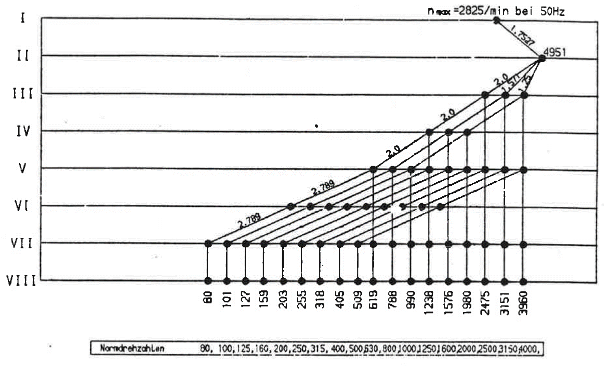
has three shifters, each positioned by a reversing geared 24VDC motor.
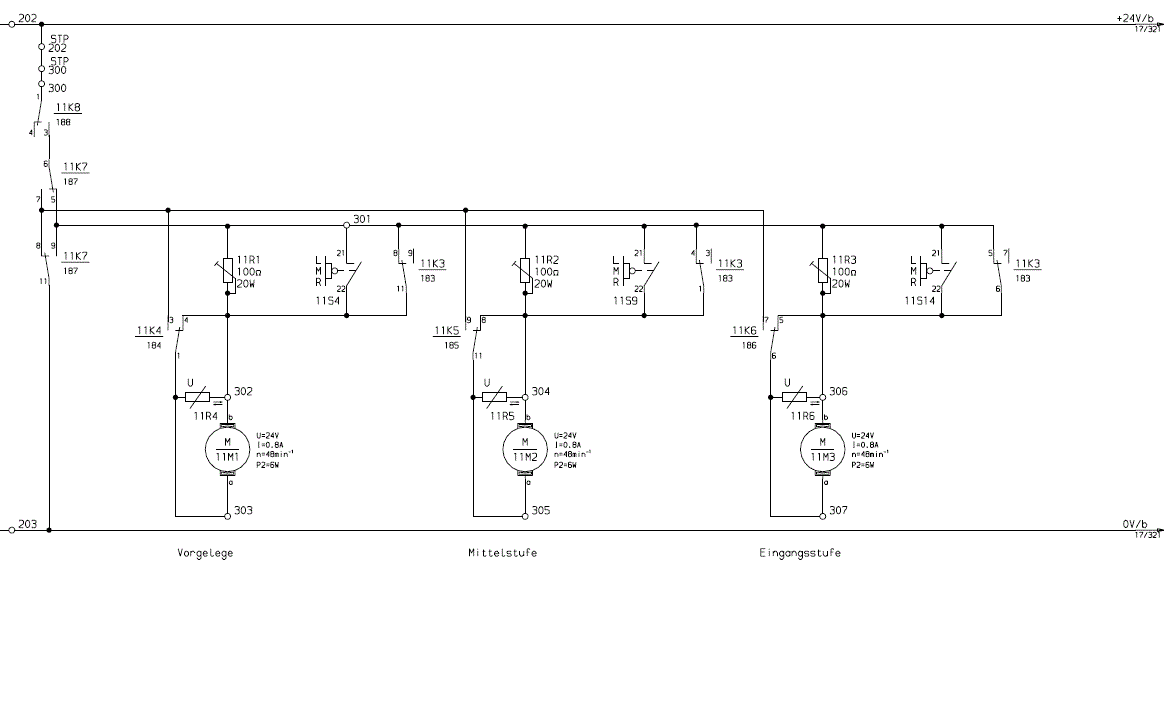
A total of 8 relays are involved in actuating the shifter motors...
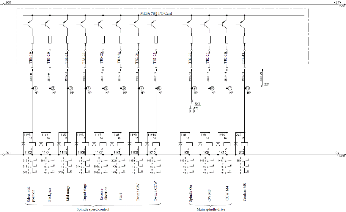
with feedback to the controller through 12 micro switches activated by cams mounted on each of the shifters.
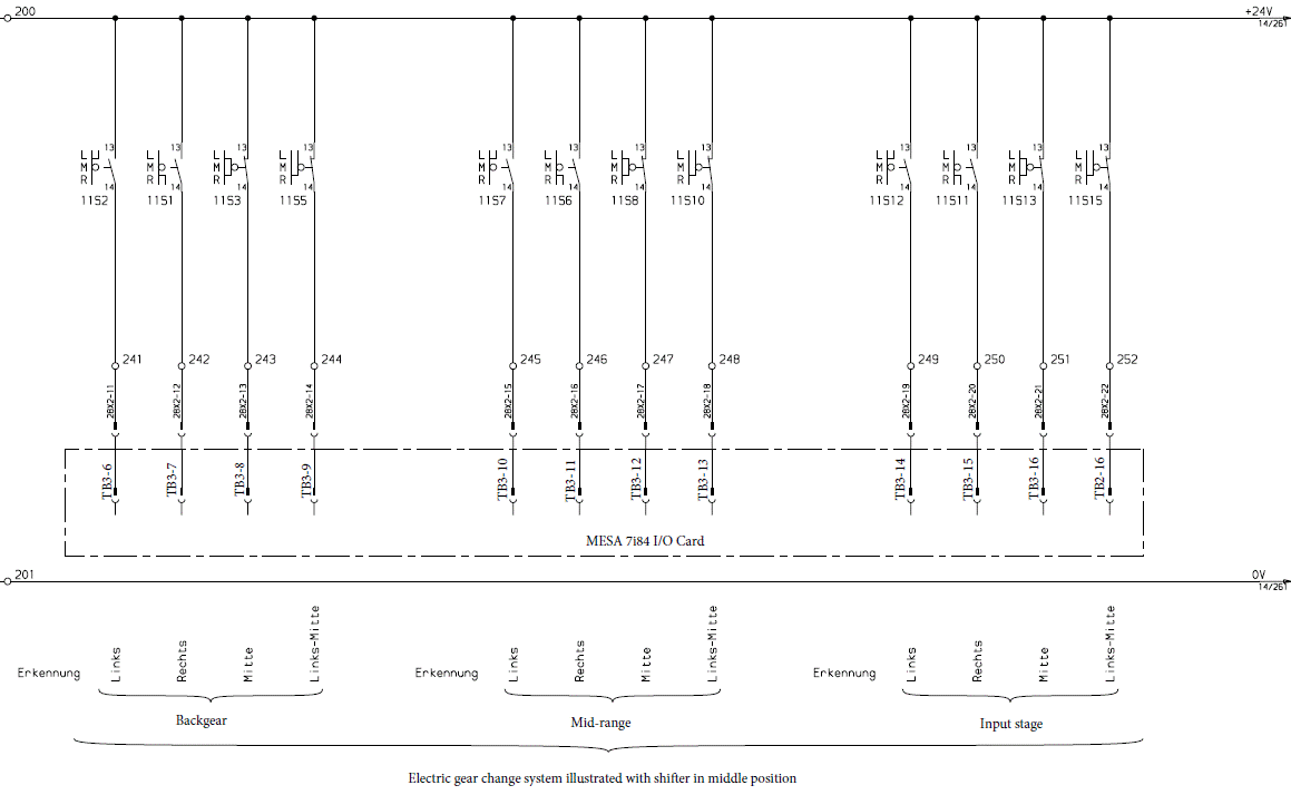
If that wasn't enough, there are also relays to twitch the main spindle motor CW and CCW during gear shift, so the gearbox doesn't bind (shown in the second to last diagram above)
And finally to ensure utter complexity, the 2.2kW 3 phase drive motor is reversable, has Star/Delta switching for no-overload starting, and a motor brake for good measure. Here is the power circuit...
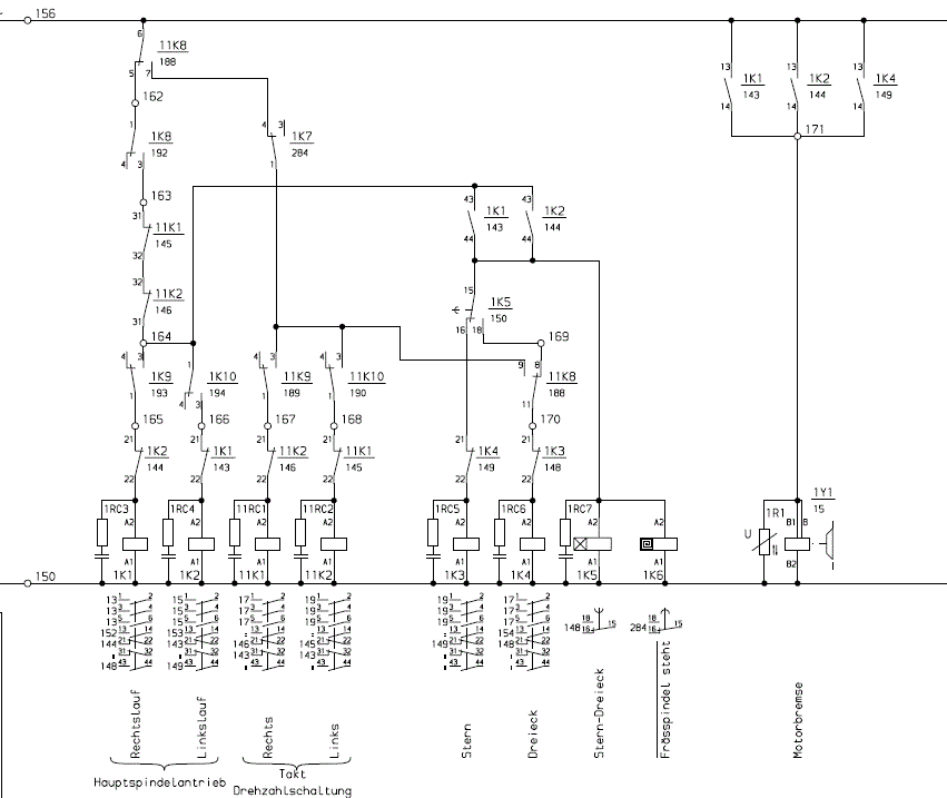
My plan is to leave the power circuit untouched. The control electrics will also be controlled by the existing MAHO relay board. So the hardware interface is simply connecting all the existing I/O pins to a 7i84.
The hard part for me is I don't really know where to start with the LinuxCNC control of this gearbox. Tying MESA 7i84 to HAL Pins seems straight forward enough, but is it better to use the Classis ladder to build up the control logic, or create a software widget. If a widget is better, then I'd prefer to use python as I have done a course in it . The system does not need to be real time as I assume you only change gear ratio on a stopped spindle. Even a rough plan of attack of how I should get started on this task would be greatly appreciated.
Mark
Please Log in or Create an account to join the conversation.
- andypugh
-
- Offline
- Moderator
-
- Posts: 19854
- Thank you received: 4635
Each gear corresponds to a pattern of relay and motor positions.
A U32 HAL pin consists of 32 bits that can encode positions.
A mux component can choose one of 18 bit patterns depending on the gear chosen.
loadrt mux_generic config="uu19"
addf mux-gen.0 servo-thread
net gear-choice pyvcp.0.gear-out => mux-gen.00.sel-int
setp mux-gen.00.in-u32-00 0  # Neutral gear
setp mux-gen.00.in-u32-01 9  # Gear 1, 00001001
...loadrt bitslice personality=10
addf bitslice.0 servo-thread
net gear-pattern mux-gen.00.out-u32 => bitslice.0.in
net actuator-0 bitslice.0.out-00 => hm2_7i84.008a.output-01
net actuator-1 bitslice.0.out-01 => hm2_7i84.008a.output-02
...loadrt weighted_sum wsum_sizes=10
loadrt comp
addf wsum.0 servo-thread
addf comp.0 servo-thread
net switch0 hm2_7i85.008a.input-02 => wsum.0.bit.0.in
net switch0 hm2_7i85.008a.input-03 => wsum.0.bit.1.in
net switch0 hm2_7i85.008a.input-04 => wsum.0.bit.2.in
...
net gear-pos-feedback wsum.0.out => comp.0.in0
net gear-pattern => comp.0.in1
net spindle-enable <= comp.0.equalPlease Log in or Create an account to join the conversation.
- RotarySMP
-
Topic Author
- Offline
- Platinum Member
-
- Posts: 1627
- Thank you received: 595
I appreciate your support.
Mark
Please Log in or Create an account to join the conversation.
- db1981
- Offline
- Platinum Member
-
- Posts: 790
- Thank you received: 276
switching this gearbox is a little bit more complex...
Important is the timing and the order of single steps.
You have to take care of the transitions between the gearstages.
For example: You can not move in one Step from the right to the left position, yoú have to switch on the center relais
wait at the midle (Spindle motor alternating a litte bit) an then go to the left. Important is also the Richtung of the little
gear shift motor, otherwise the thoots of the gears will not get together.
in attachment some measures i taken from the original PLC.
I have coded this two years ago and finished 90%. Only the evalutation of the 5 bit Gear selection switch is not ready yet. Its the machine from an neigbhour an we stopped because of an broken Axis Spindle....
I will take a review of the code, and publish if its understandable... At the moment i have many jobs, so it will take some time....
Please Log in or Create an account to join the conversation.