- Hardware & Machines
- CNC Machines
- Milling Machines
- SOLVED - Building a rotary encoder for a Leadshine MX3660
SOLVED - Building a rotary encoder for a Leadshine MX3660
- jools
-
 Topic Author
- Offline
- Elite Member
-

Less
More
- Posts: 161
- Thank you received: 15
26 Feb 2019 13:29 - 26 Feb 2019 14:26 #127157
by jools
Building a rotary encoder - Need help with electronics was created by jools
Hi All
I'm building a rotary encoder to go on my mill's spindle and am using optical sensors / photo interrupters along with a slotted disk to produce the signals. My issue is that these sensors are 5v and my BOB (MX3660 from leadshine) says that the inputs are 12v sourcing. Confusingly the data sheet for the MX3660 also says the inputs are 0-12v so I'll try them hooked straight in and see what that happens but I just wondered if anyone who'd built one had schematics / wiring diagrams on how they did it? Also does anyone know of off the shelf boards that will take the high frequency inputs and turn them from 5v to 12v in case wiring them straight doesn't work?
Or can I have the optical sensors connected straight to my parallel port via a simple opto coupler. So that when the sensor triggers the circuit is made on the Pport and the signal reads a pulse?
The other option is Hall effect sensors. But do these sense iron and steel or is it just magnets? If steel I could run them off the belt drive cog teeth.
Cheers
Jools
Last edit: 26 Feb 2019 14:26 by jools. Reason: Adding further thoughts
Please Log in or Create an account to join the conversation.
- Mike_Eitel
-

- Offline
- Platinum Member
-

Less
More
- Posts: 1052
- Thank you received: 183
26 Feb 2019 20:17 #127181
by Mike_Eitel
Replied by Mike_Eitel on topic Building a rotary encoder - Need help with electronics
Hi jools
If you make your own encoder, I guess you know electronics. So
If you have a detailed look on your bob you will find that the inputs are nothing more than a resistor driving an optocoupler on pc = 5v level.
Replacing that optocoupler with your encoder optical sensors in a direct connection should do the trick.
Mike
Please Log in or Create an account to join the conversation.
- jools
-
Topic Author
- Offline
- Elite Member
-
Less
More
- Posts: 161
- Thank you received: 15
27 Feb 2019 08:32 #127226
by jools
Replied by jools on topic Building a rotary encoder - Need help with electronics
Hi Mike
Thanks for that and I get what you mean (though I don't really know electronics; I just google stuff and ask questions till I get something that works. That probably makes me more stupid than anything") )
)
The issue with that is that my BOB is a sealed BOB and stepper drive unit from Leadshine so getting to those bits on the board would be prohibitive.
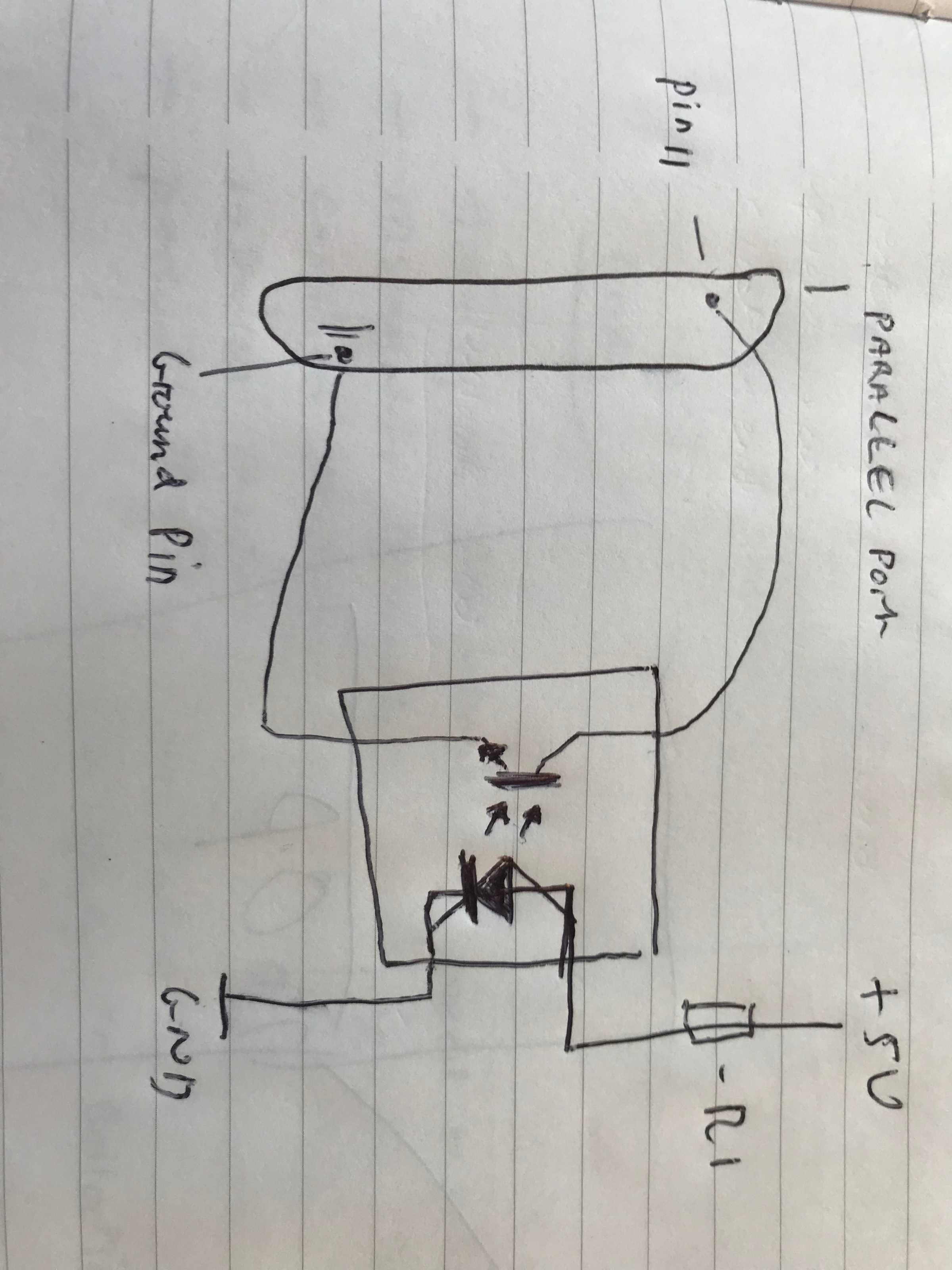
I did have a play yesterday and if I ground the parallel port wire that the pulse signal returns then the HAL meter registers this. Could I just then have the parallel port running through the collector side of the photo interruptor so that when the state changes it grounds out and registers a pulse. Or is this bad for the parallel port / blow up my PC? like the diagram below.
Thanks for the help so far.
Jools
Thanks for that and I get what you mean (though I don't really know electronics; I just google stuff and ask questions till I get something that works. That probably makes me more stupid than anything
)The issue with that is that my BOB is a sealed BOB and stepper drive unit from Leadshine so getting to those bits on the board would be prohibitive.
I did have a play yesterday and if I ground the parallel port wire that the pulse signal returns then the HAL meter registers this. Could I just then have the parallel port running through the collector side of the photo interruptor so that when the state changes it grounds out and registers a pulse. Or is this bad for the parallel port / blow up my PC? like the diagram below.
Thanks for the help so far.
Jools
Attachments:
Please Log in or Create an account to join the conversation.
- tommylight
-

- Offline
- Moderator
-

Less
More
- Posts: 21670
- Thank you received: 7401
27 Feb 2019 09:14 #127227
by tommylight
Replied by tommylight on topic Building a rotary encoder - Need help with electronics
That will work, just check if the opto sensor can handle more than 10mA of current, they usually do. Adding a resistor to one of the wires is a good idea, use a 100 Ohm one and test if it can bring the input down enough to register in hal meter.
The following user(s) said Thank You: jools
Please Log in or Create an account to join the conversation.
- Mike_Eitel
-
- Offline
- Platinum Member
-
Less
More
- Posts: 1052
- Thank you received: 183
27 Feb 2019 12:13 #127241
by Mike_Eitel
Replied by Mike_Eitel on topic Building a rotary encoder - Need help with electronics
Tommy is richtig. Restrict the current. To high current ist additionaly making the couplers slower.
Mike
Mike
Please Log in or Create an account to join the conversation.
- jools
-
Topic Author
- Offline
- Elite Member
-
Less
More
- Posts: 161
- Thank you received: 15
27 Feb 2019 12:30 - 27 Feb 2019 12:35 #127242
by jools
Replied by jools on topic Building a rotary encoder - Need help with electronics
Thanks guys I'll get on it and report back if it works and do a write uop so others can benefit.
The sensors I have are vishay tcst 2103 and the data sheet is here if you wouldn't mind letting me know if it can handle that current (as i say I'm very nooby with electronics).
Jools
The sensors I have are vishay tcst 2103 and the data sheet is here if you wouldn't mind letting me know if it can handle that current (as i say I'm very nooby with electronics).
Jools
Last edit: 27 Feb 2019 12:35 by jools. Reason: adding link to data sheet for verification
Please Log in or Create an account to join the conversation.
- tommylight
-
- Offline
- Moderator
-
Less
More
- Posts: 21670
- Thank you received: 7401
27 Feb 2019 13:59 #127245
by tommylight
Normally that would require adding another transistor, a resistor and different wiring.
Replied by tommylight on topic Building a rotary encoder - Need help with electronics
That has the current at typically 4mA, so that will most probably fail to register, but the absolute maximum current is 200mA, so i would give it a try.Thanks guys I'll get on it and report back if it works and do a write uop so others can benefit.
The sensors I have are vishay tcst 2103 and the data sheet is here if you wouldn't mind letting me know if it can handle that current (as i say I'm very nooby with electronics).
Jools
Normally that would require adding another transistor, a resistor and different wiring.
The following user(s) said Thank You: jools
Please Log in or Create an account to join the conversation.
- jools
-
Topic Author
- Offline
- Elite Member
-
Less
More
- Posts: 161
- Thank you received: 15
28 Feb 2019 16:21 #127338
by jools
Update
Tried it and it fails to register as you thought it might. Bugger.
Do you have any suggestions as to how I can wire it to make it work at all?
Jools
Replied by jools on topic Building a rotary encoder - Need help with electronics
That has the current at typically 4mA, so that will most probably fail to register, but the absolute maximum current is 200mA, so i would give it a try.Thanks guys I'll get on it and report back if it works and do a write uop so others can benefit.
The sensors I have are vishay tcst 2103 and the data sheet is here if you wouldn't mind letting me know if it can handle that current (as i say I'm very nooby with electronics).
Jools
Normally that would require adding another transistor, a resistor and different wiring.
Update
Tried it and it fails to register as you thought it might. Bugger.
Do you have any suggestions as to how I can wire it to make it work at all?
Jools
Please Log in or Create an account to join the conversation.
- tommylight
-
- Offline
- Moderator
-
Less
More
- Posts: 21670
- Thank you received: 7401
28 Feb 2019 17:14 #127340
by tommylight
Replied by tommylight on topic Building a rotary encoder - Need help with electronics
As a rough test you could wire a 1KOhm resistor to the output and try it.
Are you sure you have it wired correctly ? Try reversing the output wires.
Referring to the output from the sensor.
Are you sure you have it wired correctly ? Try reversing the output wires.
Referring to the output from the sensor.
Please Log in or Create an account to join the conversation.
- jools
-
Topic Author
- Offline
- Elite Member
-
Less
More
- Posts: 161
- Thank you received: 15
28 Feb 2019 21:16 #127360
by jools
Replied by jools on topic Building a rotary encoder - Need help with electronics
I think I may have blown the emitter side. My power supply is 4.4 amps so do you know what size resistor I would need to reduce the current down to the required level for the sensor.
I tried it though my BOB inputs too and found out that the inputs work by just creating a circuit. If I can get the power level correct to the emitter then I'll go through that.
Thanks for your help so far, you've been a god send.
Jools
I tried it though my BOB inputs too and found out that the inputs work by just creating a circuit. If I can get the power level correct to the emitter then I'll go through that.
Thanks for your help so far, you've been a god send.
Jools
Please Log in or Create an account to join the conversation.
Moderators: piasdom
- Hardware & Machines
- CNC Machines
- Milling Machines
- SOLVED - Building a rotary encoder for a Leadshine MX3660
Time to create page: 0.210 seconds