- Hardware & Machines
- CNC Machines
- Milling Machines
- SOLVED - Building a rotary encoder for a Leadshine MX3660
SOLVED - Building a rotary encoder for a Leadshine MX3660
- Grotius
-

- Offline
- Platinum Member
-

Less
More
- Posts: 2419
- Thank you received: 2348
28 Feb 2019 21:23 - 28 Feb 2019 21:45 #127361
by Grotius
Replied by Grotius on topic Building a rotary encoder - Need help with electronics
Hi Julian the cat,
If you use input 15 instead of input 11, you are better off.
Why?
It's a parport given protocol that input 15 is used for probe and faster triggering of signals.
I don't know why but it's better to use for fast input signal's. It's just like input 10 to 15 are input's instead of output's. That's the logic.
If you want to use a encoder on input 15. Use it on linuxcnc Base thread. linuxcnc Servo thread is way to slow.
So now you have 2 tip's to investegate. It will fill your evening to investegate. Good luck !!
Tommy said : That will work,
Your painting will do the job.
Look at the hal defenition text. -not for inverting signal's if needed so.
Within the Parport command's this is meaning invert signal. The parport source code has this options.
So parport.0.pin-15-in-not you can use, but you can use also parport.0.pin-15-in
I have send digital data to a pulse type encoder very, very fast via base thread and custom component in secure time of millisecond's to do the job. Finetuning took a day. With a combination of 2 very fast solid state reliais.
To fool something. It's fun. But only possible in base thread.
Last edit: 28 Feb 2019 21:45 by Grotius.
The following user(s) said Thank You: jools
Please Log in or Create an account to join the conversation.
- tommylight
-

- Away
- Moderator
-

Less
More
- Posts: 21690
- Thank you received: 7412
28 Feb 2019 21:49 #127362
by tommylight
Replied by tommylight on topic Building a rotary encoder - Need help with electronics
The "emiter" side as you call it needs about 2V to function properly, anything more and it is irreversibly destroyed.
What voltage power supply are you using ?
What voltage power supply are you using ?
The following user(s) said Thank You: Grotius
Please Log in or Create an account to join the conversation.
- Grotius
-
- Offline
- Platinum Member
-
Less
More
- Posts: 2419
- Thank you received: 2348
28 Feb 2019 21:59 #127365
by Grotius
Replied by Grotius on topic Building a rotary encoder - Need help with electronics
Tommy,
Client says he use a optical sensor. If it's 5 volt dc signal output it's okey for me to use in combination of a standard bob.
4 amp's can be a destroying power source for a optical sensor. But not if it's only used for powering the sensor. So let him
take some time to investegate the input signal's. I think it's a hal problem. I think he made a hal mistake. But soon we see that.
Please Log in or Create an account to join the conversation.
- jools
-
 Topic Author
- Offline
- Elite Member
-

Less
More
- Posts: 161
- Thank you received: 15
01 Mar 2019 11:29 #127398
by jools
Replied by jools on topic Building a rotary encoder - Need help with electronics
Hi guys
So an update is it still doesn't work") but I have more information for you.
but I have more information for you.
The power source is 5v and seems to deliver 4.4amps.
I think it's the hardware side too as I can get hal to register a signal if I use either the BOB or parallel port direct connection.
- If I wire up the reciever side (Normally open) to the gnd and +v input on my bob (no external power just creating a circuit through the connectors) the signal changes from true to false so that works.
- If I then wire up the emitter side to shine on it and close the receiver side nothing happens. Does the receiver side need voltage to close? If so how would I wire it up?
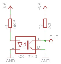
- I was using this diagram as my guide as he uses 5V power and the sensors are identical to mine.
Jools
So an update is it still doesn't work
but I have more information for you.The power source is 5v and seems to deliver 4.4amps.
I think it's the hardware side too as I can get hal to register a signal if I use either the BOB or parallel port direct connection.
- If I wire up the reciever side (Normally open) to the gnd and +v input on my bob (no external power just creating a circuit through the connectors) the signal changes from true to false so that works.
- If I then wire up the emitter side to shine on it and close the receiver side nothing happens. Does the receiver side need voltage to close? If so how would I wire it up?
- I was using this diagram as my guide as he uses 5V power and the sensors are identical to mine.
Jools
Please Log in or Create an account to join the conversation.
- Mike_Eitel
-

- Offline
- Platinum Member
-
Less
More
- Posts: 1052
- Thank you received: 183
01 Mar 2019 11:50 #127399
by Mike_Eitel
Replied by Mike_Eitel on topic Building a rotary encoder - Need help with electronics
That looks generally good.
So go back to first field and see the behavior by manually blocking the light beam with a sheet of xxx.
If you have not connected the bob : what are the two voltages at the out pin.
And what are they when the bob is connected to the out pin.
And I guess that the normal light is not disturbing.
Mike
So go back to first field and see the behavior by manually blocking the light beam with a sheet of xxx.
If you have not connected the bob : what are the two voltages at the out pin.
And what are they when the bob is connected to the out pin.
And I guess that the normal light is not disturbing.
Mike
The following user(s) said Thank You: jools
Please Log in or Create an account to join the conversation.
- jools
-
Topic Author
- Offline
- Elite Member
-
Less
More
- Posts: 161
- Thank you received: 15
04 Mar 2019 12:40 #127686
by jools
Replied by jools on topic Building a rotary encoder - Need help with electronics
UPDATE:
I tried lowering the resistor on the emitter side as no matter how low it went the reciever side never fully closed. As my BOB just needs a circuit making I think this is the issue in that it doesn't change it's state.
I think I've now blown all three sensors so have ordered more, plus a breadboard and some solid state relays. I will wire these up as the picture in my previous post and see how that gets along.
I will update again when I have that all in place as waiting on deliveries.
Jools
Please Log in or Create an account to join the conversation.
- tommylight
-
- Away
- Moderator
-
Less
More
- Posts: 21690
- Thank you received: 7412
05 Mar 2019 01:18 #127742
by tommylight
They never do, they just go down enough to close the circuit.
Replied by tommylight on topic Building a rotary encoder - Need help with electronics
I tried lowering the resistor on the emitter side as no matter how low it went the reciever side never fully closed.
They never do, they just go down enough to close the circuit.
Please Log in or Create an account to join the conversation.
- pl7i92
-

- Offline
- Platinum Member
-
Less
More
- Posts: 1872
- Thank you received: 358
05 Mar 2019 09:50 #127774
by pl7i92
Replied by pl7i92 on topic Building a rotary encoder - Need help with electronics
If you use Parport
dont go Higher then 200 Holes
if you do a Indexing Long hole and 2 Electronic items you are also getting a clear rotation speed
to make treadings
There are All kind of Encoders with up to 1000pp on low cosst on the NET
With Axis or Holes quadradure with index
dont go Higher then 200 Holes
if you do a Indexing Long hole and 2 Electronic items you are also getting a clear rotation speed
to make treadings
There are All kind of Encoders with up to 1000pp on low cosst on the NET
With Axis or Holes quadradure with index
Please Log in or Create an account to join the conversation.
- jools
-
Topic Author
- Offline
- Elite Member
-
Less
More
- Posts: 161
- Thank you received: 15
09 Mar 2019 12:45 - 09 Mar 2019 20:57 #128158
by jools
Replied by jools on topic SOLVED - Building a rotary encoder for a Leadshine MX3660
Update: Solved
So the final solution was to just use the schematic wiring diagram above but instead of the output branching out I just wired the output in series through my BOB.
So on the collector side it is like this:
5V+ to BOB input +v
BOB input -V to 10k resistor
10K resistor to Photo-interrupter +ve
Photo-interrupter to -5V
For the MX3660 this works perfectly.
Now to make the slotted disk and mount them to get proper readings while playing with HAL.
Thanks all for your help.
Jools
Last edit: 09 Mar 2019 20:57 by jools. Reason: Wrong statement
Please Log in or Create an account to join the conversation.
Moderators: piasdom
- Hardware & Machines
- CNC Machines
- Milling Machines
- SOLVED - Building a rotary encoder for a Leadshine MX3660
Time to create page: 0.248 seconds