Spindle speed sensor for a Bridgeport 2J head
- rogerfries
- Offline
- Senior Member
-

- Posts: 71
- Thank you received: 4
Attachments:
Please Log in or Create an account to join the conversation.
- rootboy
-

- Offline
- Senior Member
-
- Posts: 76
- Thank you received: 25
But is twelve pluses per revolution going to suffice? Do you need to know direction as well?
Please Log in or Create an account to join the conversation.
- rogerfries
- Offline
- Senior Member
-
- Posts: 71
- Thank you received: 4
Those spots should be no problem. And since it is steel that your sensor will be reading you won't have to get as close to them with the sensor.
But is twelve pluses per revolution going to suffice? Do you need to know direction as well?
I think 12 pulses per rev would be enough for a simple speed indicator, but If I'm going to tear into this I'd like to get a full encoder so perhaps I can try some rigid tapping.
What if I took this part and machined off some or all of the 12 ridges so I can press on a custom made gear tooth ring?
www.machinerypartsdepot.com/product/1561
I'd buy a new part to try it out os so I can revert to back stock ahould this idea turn into a horror show.
This raises the question, How much resolution is needed to do this right? how small can I make the teeth so the sensor can pick them up acurately? Can I achieve sufficiant resolution on this reletively small wheel to do thinks like rigid tapping?
What do you guys think? Thanks!
Please Log in or Create an account to join the conversation.
- OT-CNC
- Offline
- Platinum Member
-

- Posts: 617
- Thank you received: 75
Keep in mind that if you go off the vari disk or the top mount like I did, you will get accurate rpm only in normal gear. Back gear will be a different ratio and will mess with the index.
Do you have any exploded views of your spindle? I'm curious on the section that houses the z drive where the stepper is. I'm picturing hanging an encoder off the side driving it with a thin timing belt off the splined shaft. Maybe there is enough room?
Please Log in or Create an account to join the conversation.
- Mike_Eitel
-

- Offline
- Platinum Member
-
- Posts: 1052
- Thank you received: 183
Please Log in or Create an account to join the conversation.
- rootboy
-
- Offline
- Senior Member
-
- Posts: 76
- Thank you received: 25
Those spots should be no problem. And since it is steel that your sensor will be reading you won't have to get as close to them with the sensor.
But is twelve pluses per revolution going to suffice? Do you need to know direction as well?
I think 12 pulses per rev would be enough for a simple speed indicator, but If I'm going to tear into this I'd like to get a full encoder so perhaps I can try some rigid tapping.
What if I took this part and machined off some or all of the 12 ridges so I can press on a custom made gear tooth ring?
www.machinerypartsdepot.com/product/1561
I'd buy a new part to try it out os so I can revert to back stock ahould this idea turn into a horror show.
This raises the question, How much resolution is needed to do this right? how small can I make the teeth so the sensor can pick them up acurately? Can I achieve sufficiant resolution on this reletively small wheel to do thinks like rigid tapping?
What do you guys think? Thanks!
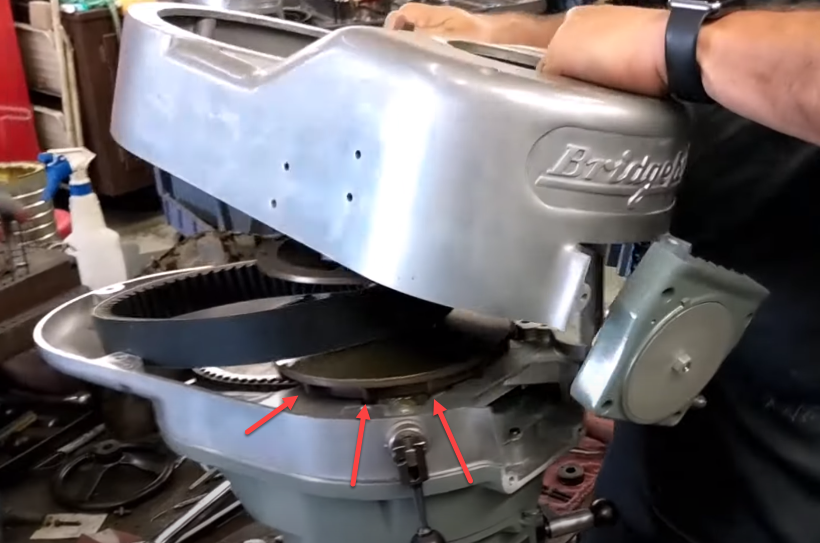
Before I modded the lower pulley half, I would put the tooth ring on the top pulley and mount the sensors through the top cover looking down. Take a look at the video that you provided at about the 11 minute mark. Looks to be plenty of room available to you, and little to no machining for you to have to do.
Drill and tap a second hole inside of the ring and mount a bolt in it. Add a sensor for this, and this can now be used as your marker pulse.
As for resolution, I guess the answer would be how tight of a tolerance do you need to keep the thread cutting to? I'm no machinist, but I can't imagine 5 - 10 degrees making all that much difference.
And rather than worrying about a ton of teeth on the tooth ring, put a second sensor halfway between the teeth. This will in effect give you double the amount of teeth for the price of a sensor.
It should, but wouldn't have to be, mounted as precisely as possible to the midway point between the teeth. Simply run the finished setup, and calculate the trigger point of the midway tooth compared to the primary sensor. Then it's a matter of adding an offset that will in effect "center" the sensor on the tooth for you.
Put another sensor offset from the first sensor by half a tooth and you will get direction as well.
The four sensors can be wired to an Arduino to create the finished encoder pulses for you.
Please Log in or Create an account to join the conversation.
- OT-CNC
- Offline
- Platinum Member
-
- Posts: 617
- Thank you received: 75
Before I modded the lower pulley half, I would put the tooth ring on the top pulley and mount the sensors through the top cover looking down. Take a look at the video that you provided at about the 11 minute mark. Looks to be plenty of room available to you, and little to no machining for you to have to do.
The top pulley moves up and down to allow for speed change. You can't easily pickup off of that.
Unless I'm mistaken, the index should be 1:1 with the spindle (tool) rotation if you want to do complex tapping. Single pass tapping should not matter as it will start tapping when the index comes around regardless of scaling. You're just out of luck if you want to go back and re-tap as it will not sync up if you're going off the top drive and you're in back gear. Does that make sense?
Please Log in or Create an account to join the conversation.
- rootboy
-
- Offline
- Senior Member
-
- Posts: 76
- Thank you received: 25
And you completely lost me on the "top drive" and "back gear". The bottom pulley is fixed to the spindle, how would its relationship to the spindle change?
But the additional sensors would still work to increase your resolution (with no need to modify the bottom pulley),
Or like what Mike suggested, mount a ring of magnets, although I'm not sure where you would mount them to where they would be able to be picked up by a Hall effect sensor.
Ah! Looking at the picture of the part that you provided (I finally noticed it...), I see where you would machine the inside of the pulley. Going back to Mike's suggestion, epoxying the magnets to the inside of the pulley would work fine. Or go with a tooth ring, either or.
The pickup(s) would be mounted to the plate that covers the gearbox below.
Please Log in or Create an account to join the conversation.
- OT-CNC
- Offline
- Platinum Member
-
- Posts: 617
- Thank you received: 75
And you completely lost me on the "top drive" and "back gear". The bottom pulley is fixed to the spindle, how would its relationship to the spindle change?
You have a variable drive mechanism (the 2 cone pulleys) that in normal drive mode lock to a splined gear hub shaft. When you move the backgear lever, the shaft separates and becomes driven by the backgear. The vari-disk always turns a timing belt that drives a gear that engages the backgear when the lever is moved. Power is only transmitted through the lower splined gear hub. #33
www.machinerypartsdepot.com/store/1478157/page/547181
Edit:
You can see how the backgear moves up/down in the video around the 1 min mark. The gear is part of the splined hub.
Please Log in or Create an account to join the conversation.
- rootboy
-
- Offline
- Senior Member
-
- Posts: 76
- Thank you received: 25
Please Log in or Create an account to join the conversation.