Fehlmann Picomax 100 Retrofit
- anfänger
-
 Topic Author
- Offline
- Platinum Member
-

Less
More
- Posts: 627
- Thank you received: 256
21 Nov 2021 21:13 #227233
by anfänger
Replied by anfänger on topic Fehlemann Picomax 100 Retrofit
Before assembly there has to be chaos. I removed the unused 24v ac circuit and the 6v ac circuit for the machine light. Also removes the 12 dc circuit for the microscope I don’t have including the power supplies.

also moved the encoder lines and the analog servo control to the place where Mesa boards will be. Did this after I removed the old control completely.

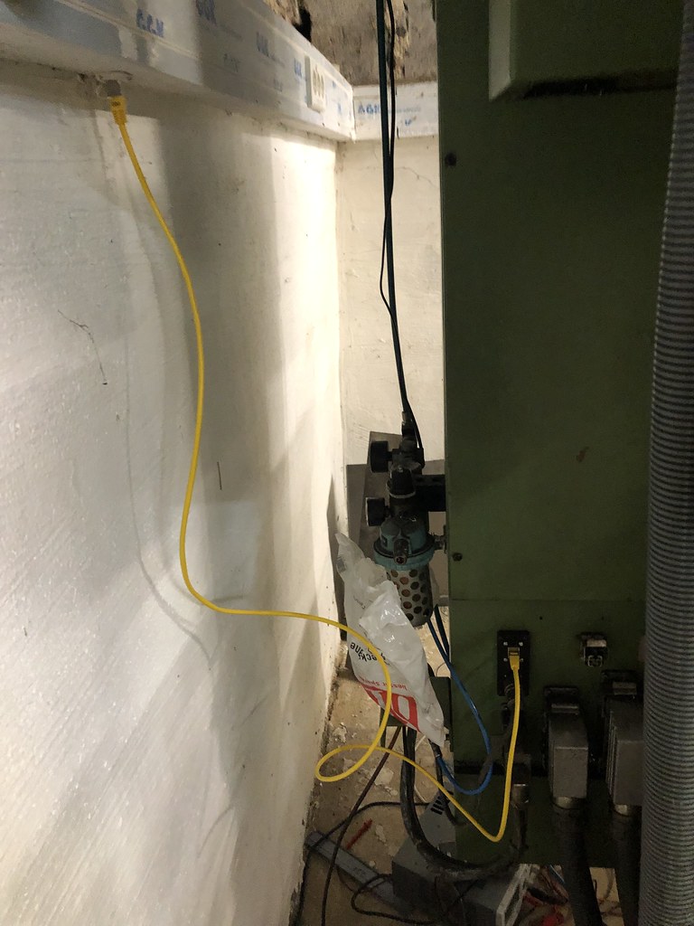
I decided to use a wireless mpg, so I removed everything including the connectors. This way I was able to reuse the hole for the connector for the Ethernet connector.

did I mention it was one of the best ideas to use the parapet channel in the shop. So it was a quick job to route an additional Ethernet connection to the machine.
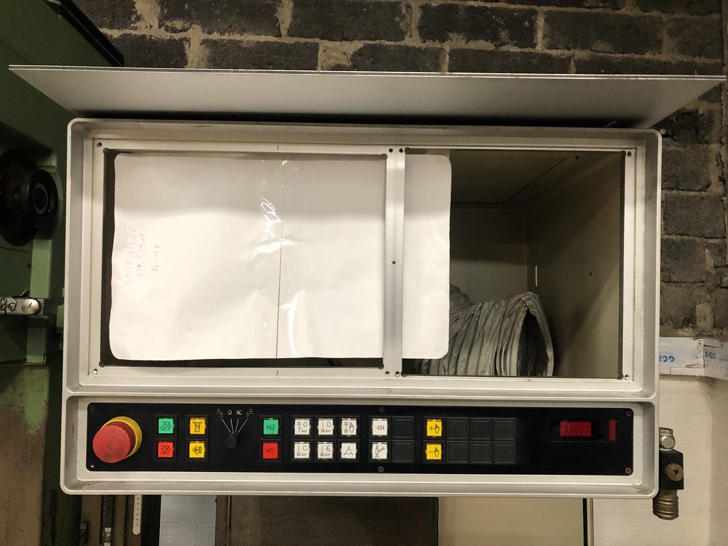
it was the first step towards reassembly. Next ist to tinker around how to mount the computer
 [/url]
the front alloy frame is really beefy so I can use it for mounting the computer.
also moved the encoder lines and the analog servo control to the place where Mesa boards will be. Did this after I removed the old control completely.
I decided to use a wireless mpg, so I removed everything including the connectors. This way I was able to reuse the hole for the connector for the Ethernet connector.
did I mention it was one of the best ideas to use the parapet channel in the shop. So it was a quick job to route an additional Ethernet connection to the machine.
it was the first step towards reassembly. Next ist to tinker around how to mount the computer
the front alloy frame is really beefy so I can use it for mounting the computer.
The following user(s) said Thank You: tommylight
Please Log in or Create an account to join the conversation.
- anfänger
-
Topic Author
- Offline
- Platinum Member
-
Less
More
- Posts: 627
- Thank you received: 256
23 Nov 2021 15:19 #227412
by anfänger
Replied by anfänger on topic Fehlemann Picomax 100 Retrofit
At the moment the Z column can go to three (five if you include top and bottom) heights automatically. The positions are set by moving the cams for the position switches. YOu you’ll always move the column manually to any Pictionary within its travel. There is no real feedback from the column on what height it is. I wonder If I could / should change that.
First thing I had in mind was to treat it as an axis and add Glas scale.
But the motor to move the column can only get the signals up, down and Pos 1-5. And has an brake amplifier, so setting up an axis with pid doesn’t seam to be an good idea. And I have to deal with the kinematics of the column and the quill moving the Z axis.
Second thought was using a glas scale and external offsets. This looks for a damn simple solution for me. Only two question come to my mind. Soft limits I read the manual, but didn’t get it. I want soft limits for the quill travel and could calculate theoretical limits for the whole Z axis which would be 0 and -730mm. This way the Quill won’t ram itself on to the table (which it could when moving the column down).
Can this be done? Are external offsets stored on shutdown (I susially store machine coordinates)? Does it male sense? Are there some better solutions out there?
Thanks Patrick
Please Log in or Create an account to join the conversation.
- anfänger
-
Topic Author
- Offline
- Platinum Member
-
Less
More
- Posts: 627
- Thank you received: 256
24 Nov 2021 14:57 #227500
by anfänger
Replied by anfänger on topic Fehlemann Picomax 100 Retrofit
Damn I looked at the external offset samples and I think they are made for something different. They result in an actual movement of the machine. I could invert the signal, so the machine tries to keep the quill in the same height when the column is moved.
At the moment I don‘t know how I can use an encoder feedback from the column to enhance the capabilities of the machine.
But it is not essential to have the feature to get the machine running. So this will be postponed.
At the moment I don‘t know how I can use an encoder feedback from the column to enhance the capabilities of the machine.
But it is not essential to have the feature to get the machine running. So this will be postponed.
Please Log in or Create an account to join the conversation.
- anfänger
-
Topic Author
- Offline
- Platinum Member
-
Less
More
- Posts: 627
- Thank you received: 256
27 Nov 2021 12:17 #227735
by anfänger
Replied by anfänger on topic Fehlemann Picomax 100 Retrofit
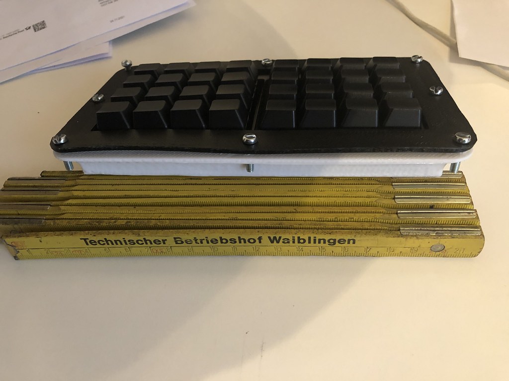
the Mesa boards are still stuck in customs, so I took the time to bring my Ideas from cardboard to CAD

in the void right to the computer will com a 3d printer holder for the programmable key pads.
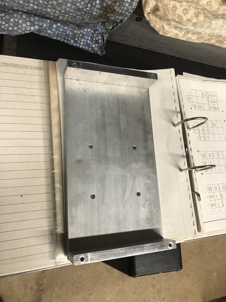
Found some 150x12mm aluminium in the shop which I can use for the computer and will be bolted to the existing quite beefy aluminium frame.
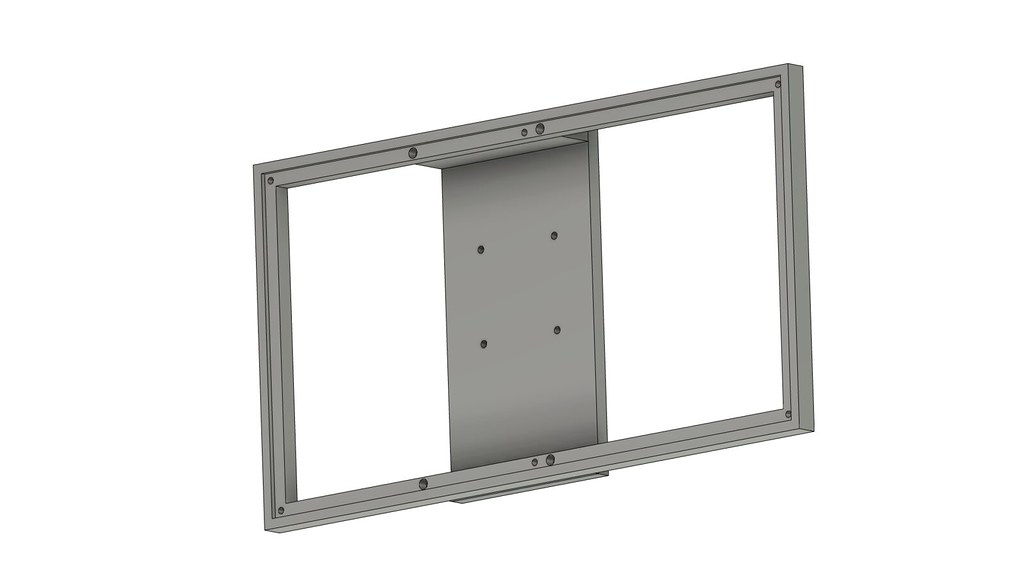
in the next days I will prepare the aluminum parts. The cover I sent out for laser cutting out of 3.2 mm aluminum plastic laminate stuff. I the end this might look rather professional compare to my other retrofits (But I am quite sure I find a ways to make it look trashy)
in the void right to the computer will com a 3d printer holder for the programmable key pads.
Found some 150x12mm aluminium in the shop which I can use for the computer and will be bolted to the existing quite beefy aluminium frame.
in the next days I will prepare the aluminum parts. The cover I sent out for laser cutting out of 3.2 mm aluminum plastic laminate stuff. I the end this might look rather professional compare to my other retrofits (But I am quite sure I find a ways to make it look trashy)
The following user(s) said Thank You: tommylight
Please Log in or Create an account to join the conversation.
- anfänger
-
Topic Author
- Offline
- Platinum Member
-
Less
More
- Posts: 627
- Thank you received: 256
04 Dec 2021 17:09 #228353
by anfänger
Replied by anfänger on topic Fehlemann Picomax 100 Retrofit
Not much progress over the last time.
but I printed a sheet to mount the USB ports in and the switch for the control power.
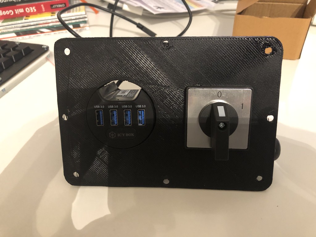 the keypads arrived and I printed a carrier to later mount the on the interface

Monday I can pick up my mesa boards, the all the hardware, except the laser cut sheet and the hand wheel has arrived.

but I printed a sheet to mount the USB ports in and the switch for the control power.
Monday I can pick up my mesa boards, the all the hardware, except the laser cut sheet and the hand wheel has arrived.
The following user(s) said Thank You: tommylight
Please Log in or Create an account to join the conversation.
- anfänger
-
Topic Author
- Offline
- Platinum Member
-
Less
More
- Posts: 627
- Thank you received: 256
05 Dec 2021 18:07 #228396
by anfänger
Replied by anfänger on topic Fehlemann Picomax 100 Retrofit
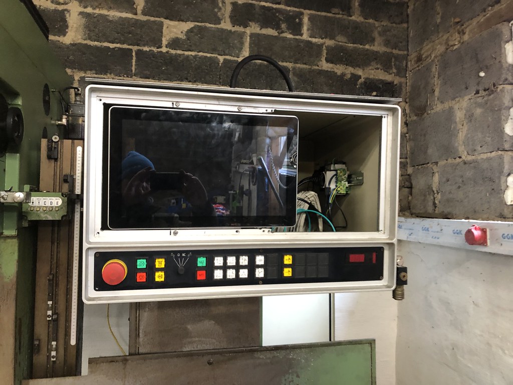
With the Mesa boards ready for pickup, I found the motivation to make some progress and made the monitor mount.
This took longer than expected cause the reference switch on the Y-Axis got stuck. But after a some massaging the old machine worked again
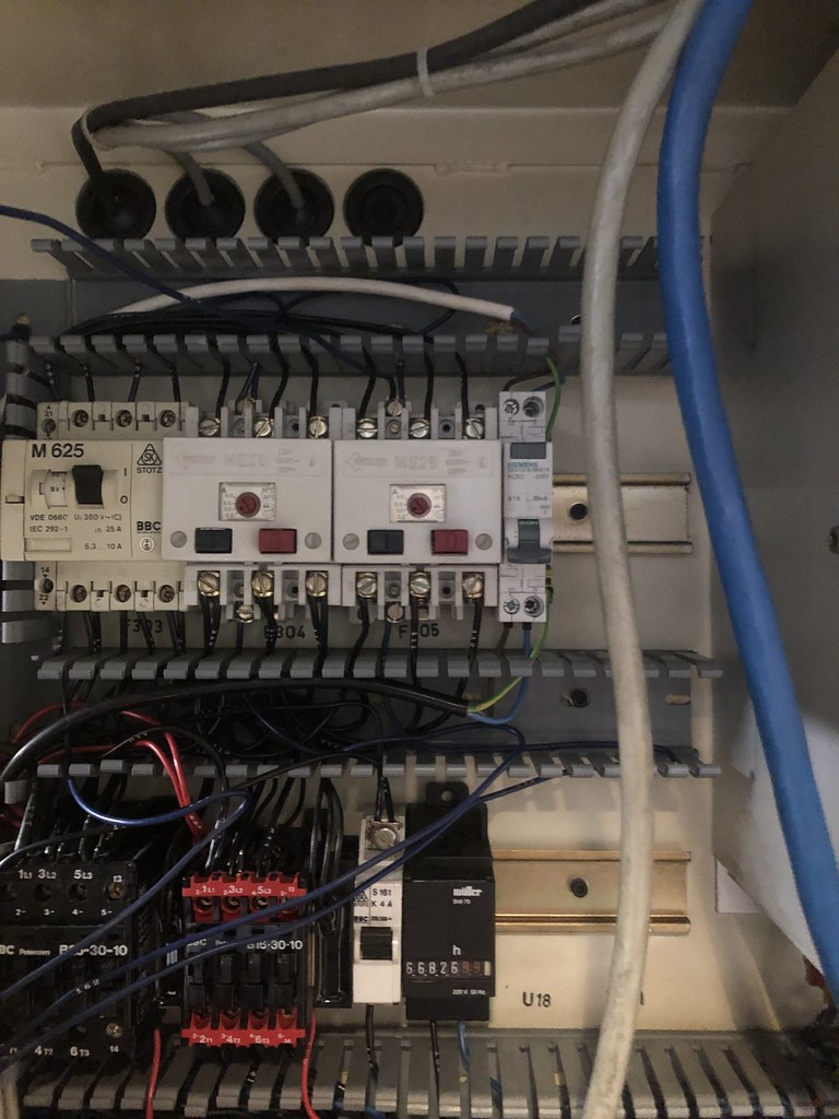
The control power supply got a new breaker with an integrated ELCB. Wich is also providing power to the socket on the control panel.
the I Installed the New 24V and 5V power supplies
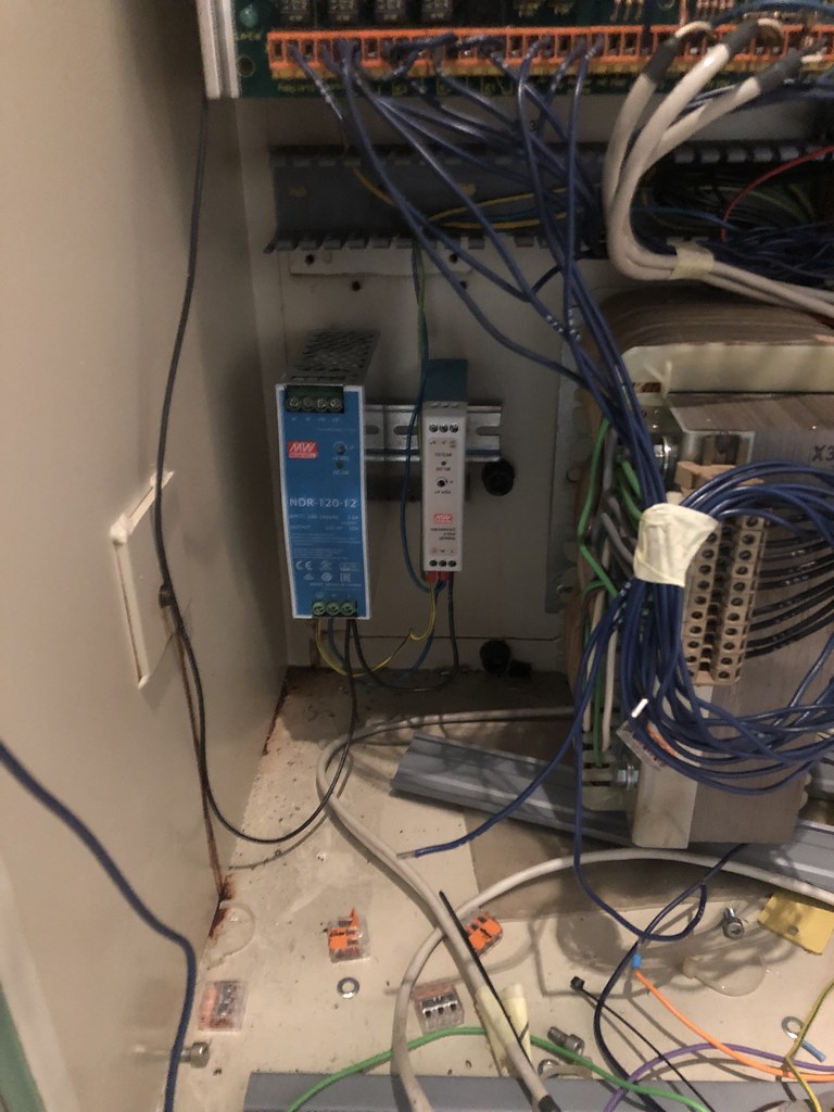
last step was preparing the din rails and wiring channel for the mesa boards:

Thats all for today.
Cheers Patrick
This took longer than expected cause the reference switch on the Y-Axis got stuck. But after a some massaging the old machine worked again
The control power supply got a new breaker with an integrated ELCB. Wich is also providing power to the socket on the control panel.
the I Installed the New 24V and 5V power supplies
last step was preparing the din rails and wiring channel for the mesa boards:
Thats all for today.
Cheers Patrick
The following user(s) said Thank You: tommylight
Please Log in or Create an account to join the conversation.
- anfänger
-
Topic Author
- Offline
- Platinum Member
-
Less
More
- Posts: 627
- Thank you received: 256
09 Dec 2021 20:59 #228730
by anfänger
Replied by anfänger on topic Fehlemann Picomax 100 Retrofit
the mesa boards are here ant Iv'e tested then
ping for first contact:

Second contact with sserial board

third contact linuxcnc

I am happy! everything seems to run, so its time to bring everything to the machine...
time to bring everything to the machine...
ping for first contact:
Second contact with sserial board
third contact linuxcnc
I am happy! everything seems to run, so its time to bring everything to the machine...
time to bring everything to the machine...
The following user(s) said Thank You: tommylight
Please Log in or Create an account to join the conversation.
- anfänger
-
Topic Author
- Offline
- Platinum Member
-
Less
More
- Posts: 627
- Thank you received: 256
12 Dec 2021 20:09 - 12 Dec 2021 20:12 #228943
by anfänger
Replied by anfänger on topic Fehlemann Picomax 100 Retrofit
found the time this weekend to finish the control power switch:
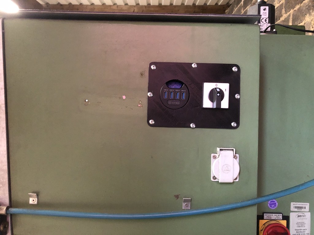

this was the last step needed to mount the computer. So I installed the mounting bracket

and then the computer:
this was the last step needed to mount the computer. So I installed the mounting bracket
and then the computer:
Last edit: 12 Dec 2021 20:12 by anfänger.
Please Log in or Create an account to join the conversation.
- anfänger
-
Topic Author
- Offline
- Platinum Member
-
Less
More
- Posts: 627
- Thank you received: 256
12 Dec 2021 20:21 #228945
by anfänger
Replied by anfänger on topic Fehlemann Picomax 100 Retrofit
Later printed out the spreadsheet for relocating the old wires

then it was time to start the wiring by mounting the mesa boards to the din rails

in the end I was able to rewire the first three connectors.

and the 5V power supply is ready, but while doing this realized that the spindle has no encoder, I didn't know how that could slip my attention, at the moment it uses an analog tachometer for feedback to the VFD. So I have to figure out what I will do about it.
then it was time to start the wiring by mounting the mesa boards to the din rails
in the end I was able to rewire the first three connectors.
and the 5V power supply is ready, but while doing this realized that the spindle has no encoder, I didn't know how that could slip my attention, at the moment it uses an analog tachometer for feedback to the VFD. So I have to figure out what I will do about it.
The following user(s) said Thank You: tommylight
Please Log in or Create an account to join the conversation.
- anfänger
-
Topic Author
- Offline
- Platinum Member
-
Less
More
- Posts: 627
- Thank you received: 256
14 Dec 2021 06:05 #229040
by anfänger

Inputs are done, analog Outputs and some of the digital outs. But more to come
Replied by anfänger on topic Fehlemann Picomax 100 Retrofit
Inputs are done, analog Outputs and some of the digital outs. But more to come
The following user(s) said Thank You: tommylight
Please Log in or Create an account to join the conversation.
Moderators: piasdom
Time to create page: 0.182 seconds