DIY CNC Mill - Random Limit Switch Errors
- zippoffs
-
 Topic Author
- Offline
- New Member
-

Less
More
- Posts: 6
- Thank you received: 7
23 Dec 2025 15:51 #340423
by zippoffs
DIY CNC Mill - Random Limit Switch Errors was created by zippoffs
Hello, I'm new to the forum. I have spent the past year and a half building my own CNC mill that runs on LinuxCNC, and it is mostly done now. Except that I can't get it to finish a program because it keeps thinking that the limit switches have been triggered even though they haven't.
I built this mill from scratch. It is made entirely of aluminum plate and extrusions. It has NEMA23 closed loop steppers, SFU1204 ballscrews, HGH20CA linear rails, a 2.2kw 220v 3 phase spindle and 2.2kw VFD, a "5 axis" parallel port breakout board, a Dell OptiPlex 990 with a parallel port card and running LinuxCNC (obviously). For limit/home switches I have it set up to where one limit switch doubles as a home switch, and all six switches are normally closed and in series all going to one input pin. The limit switches are generic micro switches, and the limit/home switches are Metrol CS067B. I have 24V running through the switches, so I'm using a 24v to 5v optocoupler board to bring the signal down to 5v for the breakout board. The Metrol switch wires are not shielded, but because they cost $67 a piece, I don't want to mess with that. The wires for the other switches are shielded.
This is what happens when I try to run a program: I home the machine, import the program into Axis, hit run, and it could be 1, 5, or 60 seconds later that it suddenly stops the machine because a limit switch was supposedly hit. It doesn't seem to happen consistently. I originally had the VFD next to the other electronics in a copper mesh cage, but ended up making a sheet metal box for it and moving it away (and took the spindle cable out of the cable chain that also held other wires). I thought that would prevent any EMI from interfering with the other electronics. But that didn't fix it. I have narrowed it down to an issue between the spindle/VFD and the breakout board. I can run a program perfectly fine with everything on except for the spindle/VFD, so it can't be the steppers or drivers. I have tried running 24v directly to the optocoupler board, bypassing the switches, but it still triggers. I have tried completely bypassing the limit switch circuit by jumping the input pin on the breakout board to ground, and it still triggers. I have spent hours researching this, and I have tried almost everything. I have my VFD in a Faraday cage. I'm using a shielded spindle cable with the shielding grounded at both ends. I have the signal wires shielded and grounded. I don't know what I'm doing wrong.
I have spent weeks trying to diagnose this, and now I am only more confused. Part of the problem is that I'm only 18 and I'm not an electrical engineer (I'm not even a mechanical engineer yet!), and I'm learning a lot of this for the first time. I have run out of things to try, and I would really appreciate any help I can get. Thank you in advance!
The following user(s) said Thank You: NWE
Please Log in or Create an account to join the conversation.
- tommylight
-

- Offline
- Moderator
-

Less
More
- Posts: 21692
- Thank you received: 7414
23 Dec 2025 20:26 #340433
by tommylight
Replied by tommylight on topic DIY CNC Mill - Random Limit Switch Errors
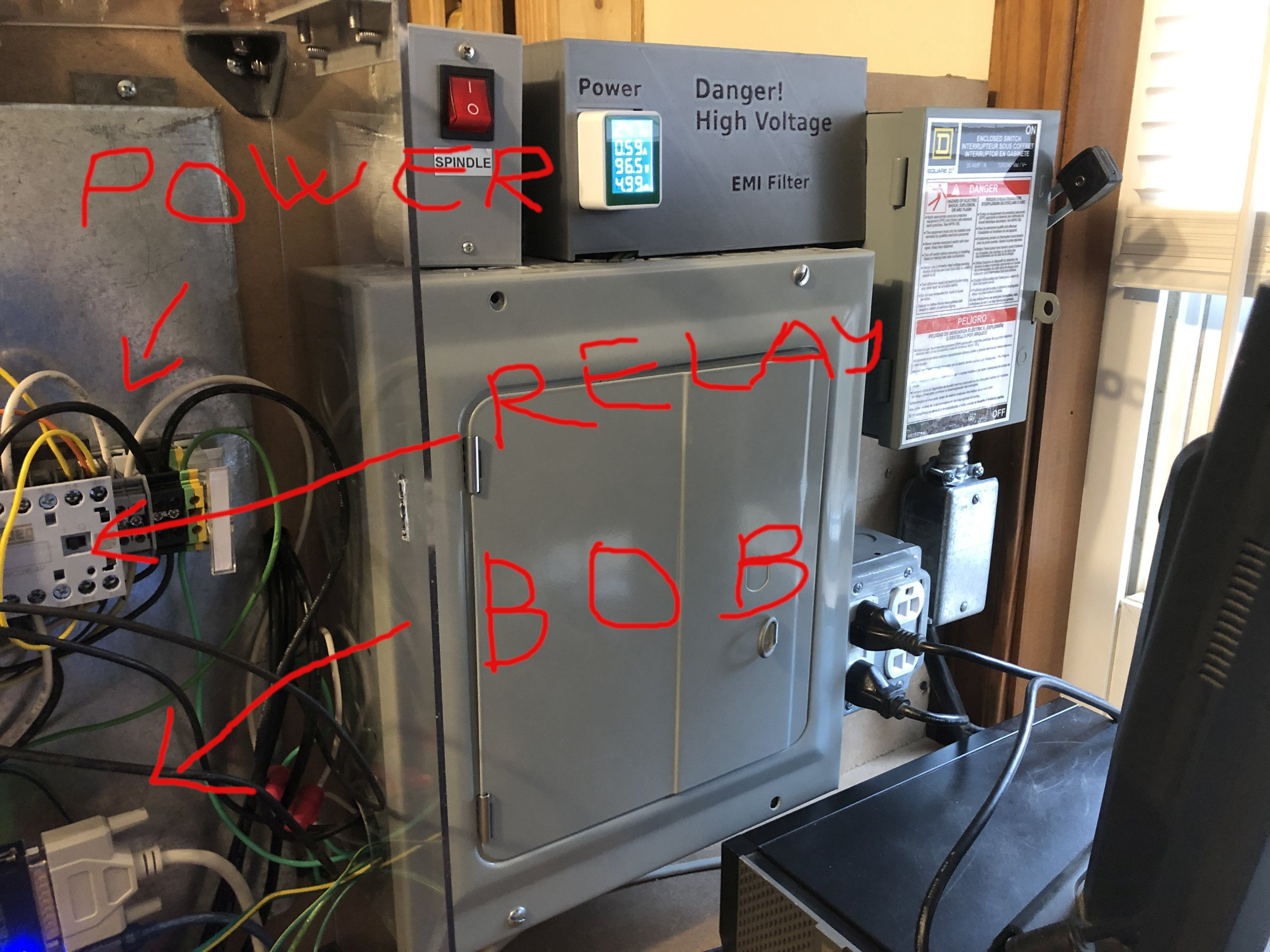
Interference issues, as seen on your second picture where the high voltage/power stuff is very close to parallel port/BOB, and messy wiring.
First make sure the grounding is OK, then move low voltage stuff as far from high voltage stuff as possible, use short cables, no spaghetti!")
First make sure the grounding is OK, then move low voltage stuff as far from high voltage stuff as possible, use short cables, no spaghetti!
Please Log in or Create an account to join the conversation.
- zippoffs
-
Topic Author
- Offline
- New Member
-
Less
More
- Posts: 6
- Thank you received: 7
23 Dec 2025 21:34 #340440
by zippoffs
Replied by zippoffs on topic DIY CNC Mill - Random Limit Switch Errors
I probably do need to go through all my grounding. However, everything functions properly if I run the program with the VFD turned off. So I don't think there is interference coming from the stuff right by the breakout board. But I have the VFD in a faraday cage, and the spindle cable shielding is grounded at both ends. What more can I do to contain the interference? Or do I need a faraday cage around the breakout board?
Do the 220v lines going from the breaker box to the VFD also emit interference?
Do the 220v lines going from the breaker box to the VFD also emit interference?
Please Log in or Create an account to join the conversation.
- tommylight
-
- Offline
- Moderator
-
Less
More
- Posts: 21692
- Thank you received: 7414
23 Dec 2025 23:27 #340443
by tommylight
I should ask WHY but....nevermind
No use, VFD already has it's own Faraday cage inside, the cabling is still outside and those are like antennae emitting interference.
Fix the cabling, separate high from low side of stuff, use short cables, see about proper grounding from Hypertherm website, ground the PC and VFD and spindle, avoid ground loops, ... and stay away from ChatGPT and Faraday cages.
Also, see The Thought Emporium on youtube about Faraday cages, they just posted a video about how hard it is to build one properly.
Replied by tommylight on topic DIY CNC Mill - Random Limit Switch Errors
I thought that was a joke when i saw the picturesBut I have the VFD in a faraday cage, ...
I should ask WHY but....nevermind
No use, VFD already has it's own Faraday cage inside, the cabling is still outside and those are like antennae emitting interference.
Fix the cabling, separate high from low side of stuff, use short cables, see about proper grounding from Hypertherm website, ground the PC and VFD and spindle, avoid ground loops, ... and stay away from ChatGPT and Faraday cages.
Also, see The Thought Emporium on youtube about Faraday cages, they just posted a video about how hard it is to build one properly.
The following user(s) said Thank You: NWE
Please Log in or Create an account to join the conversation.
- zippoffs
-
Topic Author
- Offline
- New Member
-
Less
More
- Posts: 6
- Thank you received: 7
24 Dec 2025 14:22 #340464
by zippoffs
Replied by zippoffs on topic DIY CNC Mill - Random Limit Switch Errors
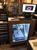
Sorry, for some reason it wouldn't upload some of my pictures.
I found a Hypertherm PDF on grounding. My conclusion is that I need a grounding rod in the ground. I do not currently have one. I will start there. And I will go through my shielding grounding to make sure that is good.
I found a Hypertherm PDF on grounding. My conclusion is that I need a grounding rod in the ground. I do not currently have one. I will start there. And I will go through my shielding grounding to make sure that is good.
The following user(s) said Thank You: tommylight, NWE
Please Log in or Create an account to join the conversation.
- NWE
-

- Offline
- Elite Member
-

Less
More
- Posts: 214
- Thank you received: 64
25 Dec 2025 03:32 - 25 Dec 2025 03:42 #340479
by NWE
Replied by NWE on topic DIY CNC Mill - Random Limit Switch Errors
All of the above (except I don't bother with an earth ground rod on mills. Plasma maybe, if its a big one). I have covered unshielded wire by wrapping in aluminum foil then cover with tape. Make sure shields are grounded at the computer end but NOT at the far end. If aluminum foil has splices, confirm it connects very good and overlaps some.
Grounding a shield at both ends can act the same as no shield. Don't ground the motor end. Spiral steel or aluminum foil is not as good as copper braid but should help.
Add ferrite beads, the more the merrier. That alone has completely mitigated some of my most annoying interference problems. I keep a bunch on hand, and just experiment by adding a couple here and there till it is fixed.
Start by putting some on each wire that's connected to the vfd, closer to the vfd is better. They absorb some of the interference the wires radiate. Next, I'd add smaller ferrites to the limit switch wires, closer to the electronics is better.
Some vfd suppliers recommend using one big ferrite and turning the three power wires around it 3x, one ferrite for the power in side, and one for the power out side.
Ferrites come in an enormous variety of shapes, sizes, and colors. I don't know how much it matters what kind of ferrite you should use. I've read there's a significant difference in different grades of ferrite. I never bothered to figure out which are better. I had a cheap USB charger transformer quit working, so I thought I'd cut the ferrite (molded in plastic) from its cord before I discard the charger. I cut it open, it was all plastic, no ferrite inside. That was a very fake ferrite.
Last edit: 25 Dec 2025 03:42 by NWE.
The following user(s) said Thank You: tommylight
Please Log in or Create an account to join the conversation.
- NWE
-
- Offline
- Elite Member
-
Less
More
- Posts: 214
- Thank you received: 64
25 Dec 2025 03:54 #340480
by NWE
Replied by NWE on topic DIY CNC Mill - Random Limit Switch Errors
I don't see a picture of the actual breakout board, and related wiring. I might be able to pinpoint good locations to add ferrites. Even the parallel cable might benefit, you'd have to use a clip-on split ferrite, but those are more expensive and I have never tried that type. Best put them on the VFD wires first. A customer watched me do that to his project and it made such a difference he asked me if it is black magic.
Please Log in or Create an account to join the conversation.
- tommylight
-
- Offline
- Moderator
-
Less
More
- Posts: 21692
- Thank you received: 7414
25 Dec 2025 05:02 #340483
by tommylight
Replied by tommylight on topic DIY CNC Mill - Random Limit Switch Errors
Attachments:
The following user(s) said Thank You: NWE
Please Log in or Create an account to join the conversation.
- NWE
-
- Offline
- Elite Member
-
Less
More
- Posts: 214
- Thank you received: 64
25 Dec 2025 05:10 - 25 Dec 2025 05:11 #340485
by NWE
Replied by NWE on topic DIY CNC Mill - Random Limit Switch Errors
BOB too close to relay and power wires.
Last edit: 25 Dec 2025 05:11 by NWE.
Please Log in or Create an account to join the conversation.
- NWE
-
- Offline
- Elite Member
-
Less
More
- Posts: 214
- Thank you received: 64
25 Dec 2025 05:20 - 25 Dec 2025 05:33 #340486
by NWE
Move VFD much closer to motor. Shorter cable from vfd to motor.
That by itself probably fix everything without doing anything else.
Also keep all DC wires far away from AC wires.
In terms of interference, the wires going from vfd to the motor are the baddest. The longer the badder. To a lesser degree all the AC wires are bad when so close to BOB and all. Contactors are also very bad the instant they open/close.
Replied by NWE on topic DIY CNC Mill - Random Limit Switch Errors
Just noticed this. It is the answer. I think.use short cables
Move VFD much closer to motor. Shorter cable from vfd to motor.
That by itself probably fix everything without doing anything else.
Also keep all DC wires far away from AC wires.
In terms of interference, the wires going from vfd to the motor are the baddest. The longer the badder. To a lesser degree all the AC wires are bad when so close to BOB and all. Contactors are also very bad the instant they open/close.
Last edit: 25 Dec 2025 05:33 by NWE.
Please Log in or Create an account to join the conversation.
Moderators: piasdom
Time to create page: 1.120 seconds