Step/Dir or Analog?
- DaBit
- Offline
- Platinum Member
-

- Posts: 446
- Thank you received: 35
Due to the fairly low resolution it is necessary to keep the bandwidth of the scale loop low. A few Hz, that's about it. Maybe with the servos it is better; more power allows quicker corrections.
In my testing (with 5u scale, BTW) I had the scale PID act on position. Thus: scale PID had position as input, position as output. 'servo' PID had position as input, velocity as output. This allowed me to limit the maximum corrrection from the scale to +/- 0,30mm. That's plenty to be effective, and little enough to prevent a runaway situation when a scale stops working.
Please Log in or Create an account to join the conversation.
- cmorley
- Away
- Moderator
-

- Posts: 7950
- Thank you received: 2160
This is very terse:
wiki.linuxcnc.org/cgi-bin/wiki.pl?Combin..._Devices_On_One_Axis
Its what Stewart did on one of his huge mills.
jmkasunich.com/cgi-bin/blosxom/shoptask/...a-trip-02-20-08.html
Please Log in or Create an account to join the conversation.
- andypugh
-

- Offline
- Moderator
-

- Posts: 23429
- Thank you received: 4979
Make sure you have the DYN-3 drives not the DYN-2. The DYN-2 can, in theory, run with 0-5V analogur command but the inputs float high, so at confog time the servos may run at full speed. Which is bad.However, I'm sticking with the servos & decided to use some driver/motors from DMM (Dynamic Motor Motion).
The DYN-3 has a proper +/- 10V drive input.
What you can do is run a conventional encoder-based position loop with the motors/drives/encoders and then add is a relatively slow, limited-authority second PID controller using the scales. Almost like a live version of screw compensation.Could you toggle between the two or use both at the same time to improve accuracy? Just wondering if it's worth while hooking up the scales.
Please Log in or Create an account to join the conversation.
- rds626
- Offline
- New Member
-

- Posts: 17
- Thank you received: 0
It's pretty cool that linuxCNC is flexible enough to implement 2 loops if one wants. I will definitely try it.
The only thing I'm looking for now is a linux version of the DMM tuning software, or if they will provide a communication/protocol spec for the DYN-3 RS232 port.
Who wants to have windows around just for motor tuning!
Please Log in or Create an account to join the conversation.
- Todd Zuercher
-

- Away
- Platinum Member
-

- Posts: 5025
- Thank you received: 1464
Please Log in or Create an account to join the conversation.
- wizard69
- Offline
- Senior Member
-

- Posts: 40
- Thank you received: 1
Another way to use glass scales and rotary encoders is to use two PIDs.
This is very terse:
wiki.linuxcnc.org/cgi-bin/wiki.pl?Combin..._Devices_On_One_Axis
Its what Stewart did on one of his huge mills.
jmkasunich.com/cgi-bin/blosxom/shoptask/...a-trip-02-20-08.html
A third way is to use the linear scale for low resolution / high speed and dynamically switch to the rotary when high resolution is required. A couple of decades ago I spent most of my working life servicing such machinery. It is an interesting approach but the manufacture did this via custom hardware and I wouldn't even want to guess at the difficulties they had developing that hardware. Most people don't have a need for such high resolution systems and frankly electronics are a lot faster these days so it is unknown to me if this can be accomplished on PC hardware.
Please Log in or Create an account to join the conversation.
- DaBit
- Offline
- Platinum Member
-

- Posts: 446
- Thank you received: 35
It made me think though: it should be possible to create a component that uses the scale counts as 'most significant digits' and add resolution using counts from the rotary.
Any mechanical play in the system would add non-monotonic behaviour though.
Regarding processing speed: current PC's or even cheap microcontrollers are blazing fast compared to the speed of the mechanics.
Please Log in or Create an account to join the conversation.
- DaBit
- Offline
- Platinum Member
-

- Posts: 446
- Thank you received: 35
Needs 2-3 more support points over the length though.
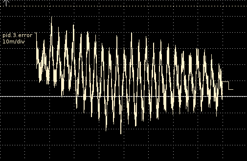
Deviation, scale vs. rotary encoder, no correction:
Scale of the graph is 0,01mm/division (0,0004"/div)
(it is fairly obvious that I have a mechanical problem. Ballscrew is not 100% straight, pulley not 100% square to the screw, and Chinese ballscrews costing $20 including end machining. This is also why I set up the scale so I can measure and take actions based on measurements instead of gut feelings).
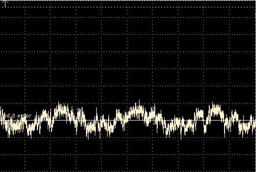
With scale correction, travel speed 1000mm/min (40ipm):
Scale of the graph is 0,01mm/division (0,0004"/div)
Keep in mind that a single scale tick is half a division...
Setup:
axis.0.motor-pos-cmd --(position)--> scale PID using only an I term for disturbance rejection --(position)--> servomotor PID ---(torque)--> motor.
Thus, the scale PID gets a position as input, the scale as feedback, and it outputs position. It's effect is limited to +/-0,15mm. The position from this PID is then fed into the servo loop.
Please Log in or Create an account to join the conversation.
- DaBit
- Offline
- Platinum Member
-

- Posts: 446
- Thank you received: 35
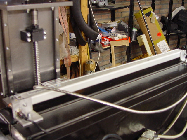
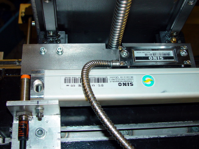
I also mounted a 1um resolution glass scale on the stepper-driven Z axis.
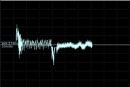
A homing sequence going up 100mm with rapid speed (4500mm/min), then down with 120mm/min, scale is 0,01mm/vertical division:
With these rapid moves I am unable to get rid of the under/overshoot. A stepper motor needs a few microsteps to develop the required torque and there is not enough margin between stepper maximum velocity/acceleration (5100mm/sec, 1200mm/sec^2) and trajectory planner allowed maximum velocity (4500mm/sec, 1000mm/sec^2) to build up this electrical angle advance quickly enough.
With lower (milling) speeds there is plenty of headroom and the over/undershoots disappear. Also visible is the lowspeed portion of the graph above.
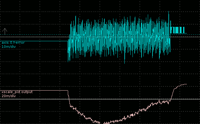
Next, given the new insights I retuned the torque-mode servo driven X-axis. Graph is a 12000mm/min move, still with slightly bent Chinese $20 ballscrew:
I re-tuned the servo-PID by starting with a low P value, center the response using FF1/FF2, and then increase P and D. Without I I got a little bit of hunting, so I used a tiny bit of I to stop that. If I could have left the I at zero I would have done so.
The rest of the integral was carried over to the scale-PID, which runs with a fairly large I only. No P, no D, no FFx.
No undershoot, no overshoot, low following error for such a high speed and inaccurate ballscrew.
Please Log in or Create an account to join the conversation.
- vre
- Offline
- Platinum Member
-

- Posts: 660
- Thank you received: 19
I want to drive servos (step+dir mode or analog velocity mode) from linuxcnc with outer closed loop.
My servos are 3000rpm get 500khz step-dir signals and output differential signals from its quadrature incremental rotary encoders (ABZ) 2500ppr (10000 with quadrature)
the signals from rotary encoder goes to servo drivers and servo drivers has an output of these signals for the controller.
I want to use the servos in a lathe cnc retrofit so i want at least 2 servos for Z and X axis.
Also i want quadrature encoder input for the spindle (threading operation), 0-10V for vfd spindle speed control and misc I/O (for limit switches)
What hardware from mesa will be suitable for this case ?
thank you.
Please Log in or Create an account to join the conversation.

