
Spindle Control 6i25+7i76 and GS3-22P0 VFD RS-485 compatible?
- tommylight
-

- Offline
- Moderator
-

On that diagram the Z output does not look like an index, in that case you can not use it for rigid taping, everything else should work.
Please Log in or Create an account to join the conversation.

tommylight wrote: That is a single ended incremental encoder, and as far as i can recal all mesa boards have jumpers for using single ended encoders, so it should be ok, just check the 7i76 manualbto be sure.
On that diagram the Z output does not look like an index, in that case you can not use it for rigid taping, everything else should work.
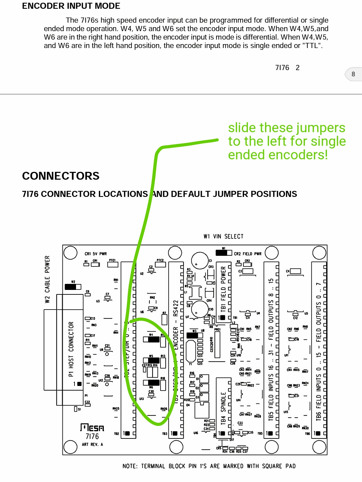
OK it appears there are jumpers w4, w5, w6 to change to single ended encoders, I wasn't aware that's what this was.. so that's solved.. sweet!!
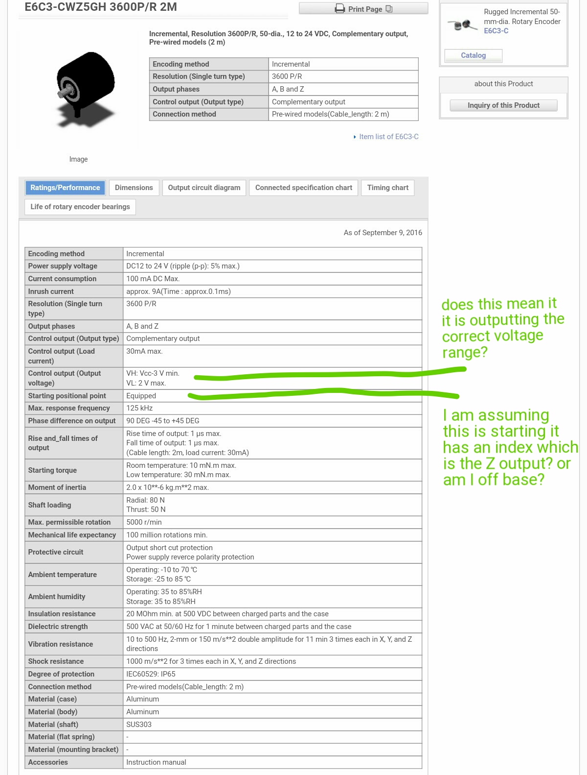
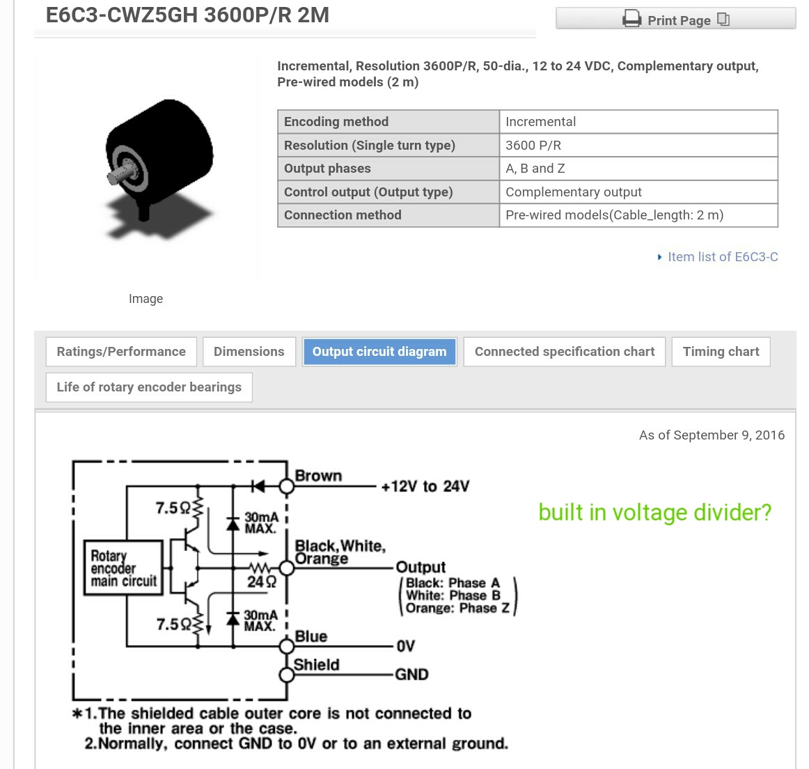
After combing through the specs again a few things jumped out at me. See the images below for reference, I marked them up with notes. I am not an electronics wiz, but from researching voltage dividers, it sort of appears that there are resistors being shown that are very close to achieving what a voltage divider would look like and the resistor sizes are very close to what the calculators are saying would be correct to do it to under 5v. Thoughts? I also saw where it shows the output as follows:
H- 3v min
L- 2v max
So I'm now wondering if the output is already the correct voltage, any thoughts here are great. I will contact omron tomorrow for verification as well.
Please Log in or Create an account to join the conversation.
- tommylight
-
- Offline
- Moderator
-
No changes to 7i76, no jumpers to move, just connect A, B, and Z, to the enc A+, enc B+, and Idx+. NOT directly !!!
Nothing in the outputs is 3V, IT IS 3V under the VCC ( in case of 12V it is 9V, in case of 24V it is 21V ) .
That is not a voltage divider, that is a "push-pull" output made of 2 transistors, so it can sink and source to the output.
Please read this before wiring the encoder,
learn.sparkfun.com/tutorials/voltage-dividers
make sure you understand how they should be wired and find some resistors that can be used as follows : You mentioned using 24V power, so to be sure that the current draw will not exceed 10mA and to easier calculate lets say a 2.4Kohm resistor (usual values 2.2 or 3.3 should do), now you need 3 to 5V at the encoder inputs on the 7i76 so that would imply 330 to 470 ohm . To recap, you need one 2.2KOhm and one 330 Ohm resistor for each channel, OR 3.3KOhm and 470Ohm.
On the pictures on that page you have Vin ( that is the output FROM the encoder ), Vout ( that is the input ON the 7i76 ) and the ground wire.
Please Log in or Create an account to join the conversation.
tommylight wrote: Here we go:
No changes to 7i76, no jumpers to move, just connect A, B, and Z, to the enc A+, enc B+, and Idx+. NOT directly !!!
Nothing in the outputs is 3V, IT IS 3V under the VCC ( in case of 12V it is 9V, in case of 24V it is 21V ) .
That is not a voltage divider, that is a "push-pull" output made of 2 transistors, so it can sink and source to the output.
Please read this before wiring the encoder,
learn.sparkfun.com/tutorials/voltage-dividers
make sure you understand how they should be wired and find some resistors that can be used as follows : You mentioned using 24V power, so to be sure that the current draw will not exceed 10mA and to easier calculate lets say a 2.4Kohm resistor (usual values 2.2 or 3.3 should do), now you need 3 to 5V at the encoder inputs on the 7i76 so that would imply 330 to 470 ohm . To recap, you need one 2.2KOhm and one 330 Ohm resistor for each channel, OR 3.3KOhm and 470Ohm.
On the pictures on that page you have Vin ( that is the output FROM the encoder ), Vout ( that is the input ON the 7i76 ) and the ground wire.
I wound up ordering a 5v encoder so I didn't make a mistake and wind up hiring something.
So going back to my original other question of VFD connection via the RS-485 connection. Is this something that is possible?
Please Log in or Create an account to join the conversation.
- tommylight
-
- Offline
- Moderator
-
You made a wise decision to get a 5V encoder, easier to cope with.
Regards,
Tom
Please Log in or Create an account to join the conversation.
Lcvette wrote: So going back to my original other question of VFD connection via the RS-485 connection. Is this something that is possible?
I would imagine so, but there isn't an existing dedicated module for it, so you would have to configure one of the generic ones.
linuxcnc.org/docs/2.7/html/drivers/mb2hal.html
Please Log in or Create an account to join the conversation.