Yaskawa usarem motors, Amc be25a20 making it work?

More
7 years 11 months ago - 7 years 11 months ago #121674 by JR1050
The paper from Yaskawa above states the a and b channels are standard incremental quad channels and the c is the marker pulse(you can see the index enable go low to high in the video). The serial data is sent thru channel A on start up, on a 15 bit encoder, then it reads incrementally. There are several manuals on these motors and drives, TSE-s800-2.4e and TSE-s800-15c do a good job at explaining how the encoder works. The wiring scheme is the same for both their incremental and absolute encoders with the exception of the battery backup being excluded on the incremental version, they call the marker/home/Z channel C on both. Ill bet they are they same .They are not gray code output.They count the specified distance on the dro based on the input scale.These are also older (1995 vintage) motors.

I am by no means an expert on this, as its new to me, but based on the info ive read and what Ive observed, Id say its looking like this will work if i can get the hall signals to output. Id bet im missing a parameter or don't have the component setup right...

This is worth figuring out, if it works it will save anyone who wants to use Yaz motors and not have to pay the big yaz drive cost.
Last edit: 7 years 11 months ago by JR1050.

Please Log in or Create an account to join the conversation.
More
7 years 11 months ago #121676 by andypugh

JR1050 wrote: Here is a short video of where I'm at, encoder counts, index channel appears to work. I'm not getting any hall signals though .


"qiH" needs you to send an "init" signal:
Code:
4 bit OUT FALSE bldc.0.hall1-out 4 bit OUT FALSE bldc.0.hall2-out 4 bit OUT FALSE bldc.0.hall3-out 4 bit I/O FALSE bldc.0.index-enable 4 bit IN FALSE bldc.0.init 4 bit OUT FALSE bldc.0.init-done 4 float IN 0.2 bldc.0.initvalue 4 float IN 90 bldc.0.lead-angle 4 float OUT 0 bldc.0.out 4 float OUT 0 bldc.0.out-abs 4 bit OUT FALSE bldc.0.out-dir 4 float OUT 0 bldc.0.phase-angle 4 s32 IN 0 bldc.0.rawcounts 4 bit IN FALSE bldc.0.rev 4 float OUT 0 bldc.0.rotor-angle 4 s32 OUT 0 bldc.0.time 4 float IN 0 bldc.0.value

That starts a search-for-index.
I would change your enable section of HAL to look like
Code:
# axis enable chain net emcmot.00.enable <= joint.0.amp-enable-out #hal pin enables the amp net emcmot.00.enable => hm2_7i90.0.pwmgen.00.enable #mesa pin enables pwm net emcmot.00.enable => bldc.0.init #magnetically home the motor net enable-X-control <= bldc.0.init-done net enable-X-control => pid.0.enable #hal pin enables pid

The bldc component is rather busy, on the man page there are several references to personality, what do these pertain to?

All references to "personality" are auto-generated and should be ignored.
(the q, i, a etc flags become a bitmask that becomes "personality" and that controls what pins are created, but the compiler doesn't know that the user shouldn't be setting those and auto-documents them)
The following user(s) said Thank You: JR1050

Please Log in or Create an account to join the conversation.

More
7 years 10 months ago - 7 years 10 months ago #122735 by JR1050
Some info, progress , issues

It took a significant effort to get info on these motors. Yaskawa motors with an FJ suffix were made for Fuji and Yaskawa USA has little to no info , but.... I do have this
All Yaskawa ac motors are 8 pole
Fuji used incremental encoders , they will be utop i or h and the number after x 10 is the count. As far as I can tell FJ11 is usually a 2000 ppr incremental. All Yaskawa encoders are the same hardware wise, they are programmed to count and absolute/incremental. That was from Yaskawa direct.
Yaskawa aligns the marker pulse with motor zero.

In the video below is the drive running the motor in current mode, it is be run off a watch battery.
My present issue is I'm not getting any analog voltage out of the 7i33, I get pid, as putting some P and D on it stiffened the shaft up. I Could the bldc component be clashing somehow with the pwm out put? Since the marker and motor zero are already aligned, does it still need magnetic homing?


Addendum.... first jogs. Motor cogs some. On the right track.
Last edit: 7 years 10 months ago by JR1050.

Please Log in or Create an account to join the conversation.
More
7 years 10 months ago #122741 by andypugh

JR1050 wrote: Since the marker and motor zero are already aligned, does it still need magnetic homing?


No, you should use "qi" mode.

But just bear in mind that "motor zero" has more than one definition. A+ B- C- is a common one (and the Mesa one) bit it is not universal.

Please Log in or Create an account to join the conversation.

More
7 years 10 months ago #122743 by JR1050
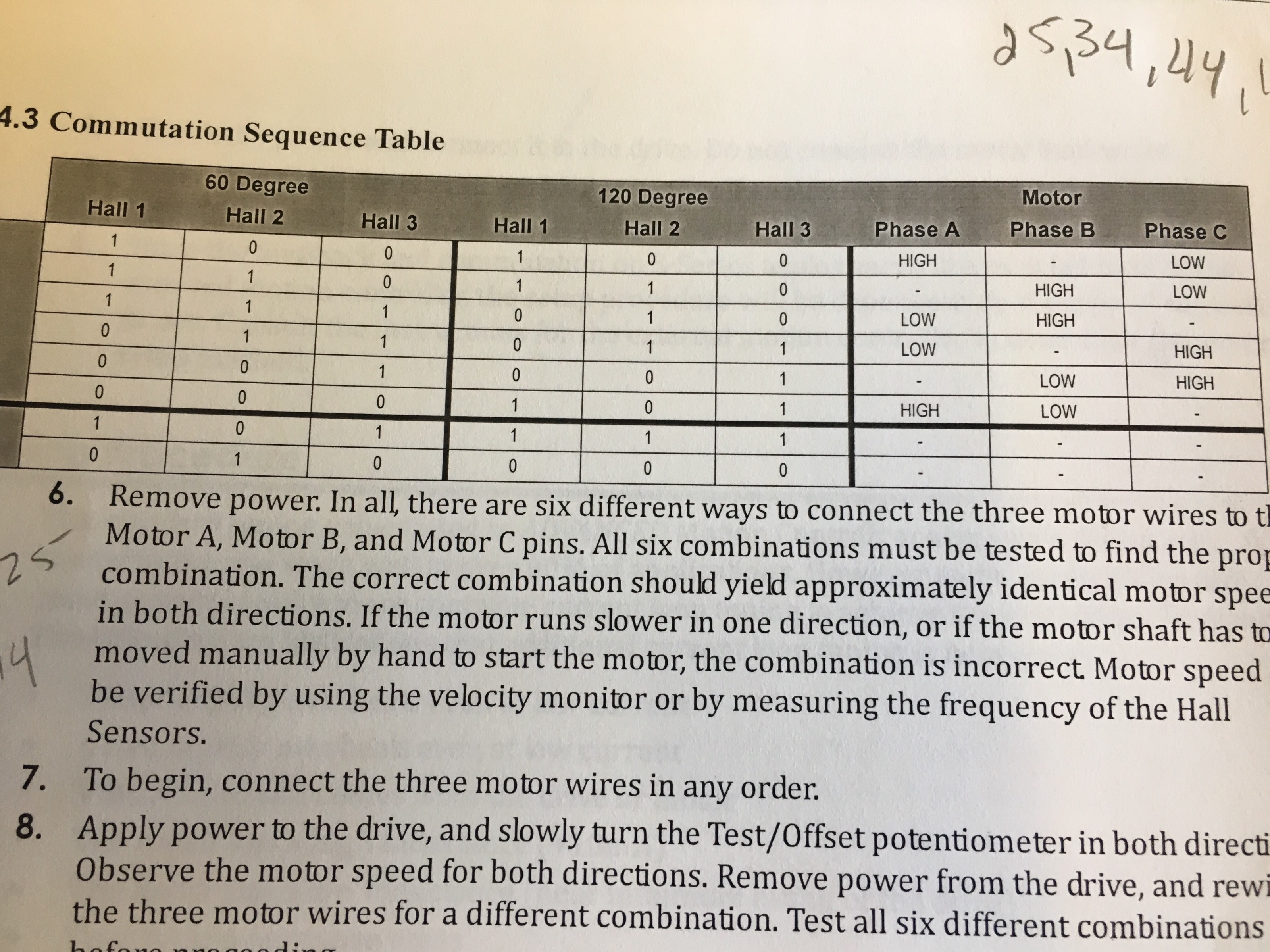
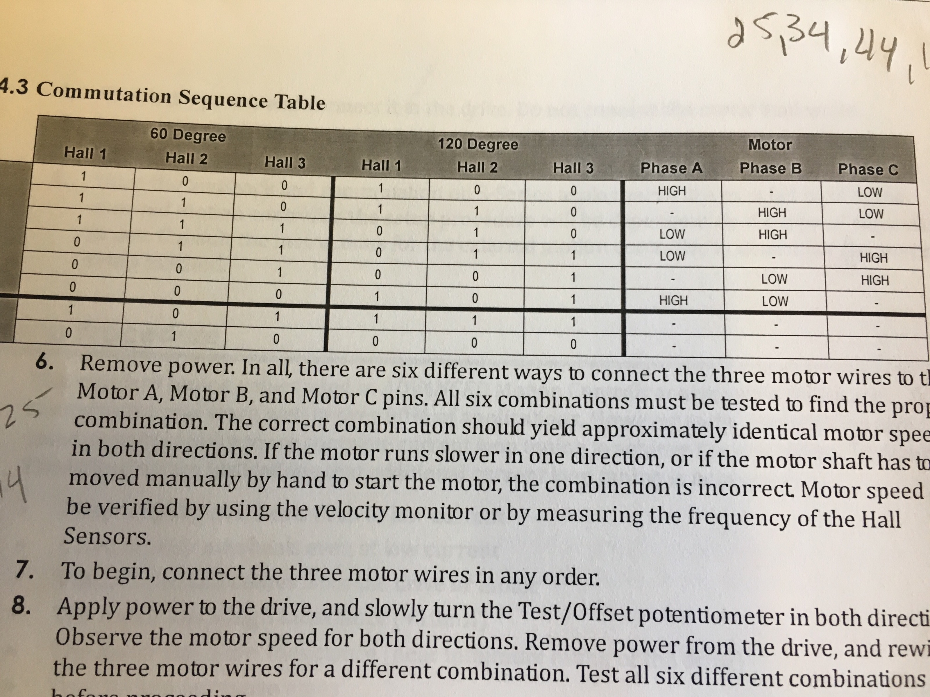
This is the chart from the Amc hardware manual for the drives. I have found that pattern 17 and 34 work, although the motor runs smoother in one direction then the other. Yaskawa considers standard motor direction to be ccw while facing the driving end of the motor. It has also occurred to me that I'm asking to much from a rspi.


Please Log in or Create an account to join the conversation.

More
7 years 9 months ago #123517 by JR1050
To use bldc , the encoder index enable has to be connected to the bldc index enable, however, the encoder index enable also has to be connected to the joint index enable. The issue:

With the encoder index enable solely connected to the bldc index enable
the motor motor homes immediately , meaning communtation is immediate. If I connect both of the mentioned pins to encoder index enable, the motor jumps all over while joint enable seems to cancel bldc
Index enable. one is setting the pin, the other is looking for it to be set.
I admit this is confusing . What is the best way for both bldc and joint index enable to share the encoder index enable with out conflicting?

Please Log in or Create an account to join the conversation.

Moderators: PCW, jmelson
Time to create page: 0.482 seconds
Powered by Kunena Forum