Does this wiring layout look ok for a starting point?
- jools
-
 Topic Author
- Offline
- Elite Member
-

Less
More
- Posts: 161
- Thank you received: 15
05 Nov 2019 09:51 - 05 Nov 2019 09:51 #149583
by jools
Does this wiring layout look ok for a starting point? was created by jools
Hi all
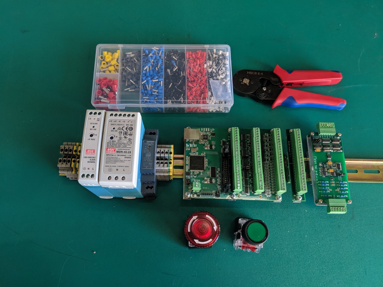
Just wiring the electronics up and wanted to start from a good base for best practice to reduce noise. I've attached two photos of how I plan to layout the electrics on the ground plane and hoped to get help so that I don't make stupid early mistakes.
- Top right is 48v power supply to motor drives
- Middle power supply is 5V for Mesa
- Bottom is 24v for home switches.
(I am planning to add a filter to the ac power that serves these three PSU's)
- Then 7i96 with 7i85s
- Leadshine easy servo motor drivers (hybrid steppers) at the top.
The only cables that will cross will be power to the drives and the output motor drive signals. All others can be routed flat to the ground plane. Shielded cables for all signals will be grounded to the ground plane and will be used for all cabling apart from power, which will use twisted pairs.
My spindle servo I was going to use a seperate ground plane to try and get some distance between them. I will also add an inline filter to this AC line.
So is there anything wrong with this setup or anything else I should do to reduce it's susceptibility to noise?
Cheers
Jools
Last edit: 05 Nov 2019 09:51 by jools. Reason: I am stupid and didn't attach photos :-)
Please Log in or Create an account to join the conversation.
- tommylight
-

- Away
- Moderator
-

Less
More
- Posts: 21662
- Thank you received: 7400
05 Nov 2019 10:37 #149590
by tommylight
Replied by tommylight on topic Does this wiring layout look ok for a starting point?
Mesa as far from power supplies as possible.
The following user(s) said Thank You: jools
Please Log in or Create an account to join the conversation.
- jools
-
Topic Author
- Offline
- Elite Member
-
Less
More
- Posts: 161
- Thank you received: 15
05 Nov 2019 10:52 #149591
by jools
Should I shorten the DB25 connector that connects the 7196 to the 7i85; It has lots of spare wire at the moment?
Replied by jools on topic Does this wiring layout look ok for a starting point?
Mesa as far from power supplies as possible.
Should I shorten the DB25 connector that connects the 7196 to the 7i85; It has lots of spare wire at the moment?
Please Log in or Create an account to join the conversation.
- tommylight
-
- Away
- Moderator
-
Less
More
- Posts: 21662
- Thank you received: 7400
05 Nov 2019 12:30 #149597
by tommylight
I would not do that, to much trouble and might end up not working due to loose contacts.
Replied by tommylight on topic Does this wiring layout look ok for a starting point?
Should I shorten the DB25 connector that connects the 7196 to the 7i85; It has lots of spare wire at the moment?
I would not do that, to much trouble and might end up not working due to loose contacts.
The following user(s) said Thank You: jools
Please Log in or Create an account to join the conversation.
- jools
-
Topic Author
- Offline
- Elite Member
-
Less
More
- Posts: 161
- Thank you received: 15
05 Nov 2019 15:48 - 05 Nov 2019 15:54 #149613
by jools
Replied by jools on topic Does this wiring layout look ok for a starting point?
OK noted.
Looks like I have to cross the encoder wires going into the 7I85. I have a choice of crossing the stepper motor driver power cables or the DIR/STEP cables; which would you go? The STEP/DIR are shielded and I'm going to use shielded for the encoder cables too, the power is just a twisted pair of unshielded.
Attachment shows what I have now.
Last edit: 05 Nov 2019 15:54 by jools. Reason: added photo
Please Log in or Create an account to join the conversation.
- pl7i92
-

- Offline
- Platinum Member
-

Less
More
- Posts: 1872
- Thank you received: 358
05 Nov 2019 16:33 #149620
by pl7i92
Replied by pl7i92 on topic Does this wiring layout look ok for a starting point?
3flat powersups in a row is not that good mount this brings in EMI for shure
and the twisted powerlines are a hell of a magnet on DC
DO NOT power the Drives without motors connected they can smoke within 1/10000
so far so good is it 1,5mm² as of 6Amps
awg 16-14 you can have double isolated cables for car audio use
and the twisted powerlines are a hell of a magnet on DC
DO NOT power the Drives without motors connected they can smoke within 1/10000
so far so good is it 1,5mm² as of 6Amps
awg 16-14 you can have double isolated cables for car audio use
Please Log in or Create an account to join the conversation.
- tommylight
-
- Away
- Moderator
-
Less
More
- Posts: 21662
- Thank you received: 7400
05 Nov 2019 16:43 #149621
by tommylight
Replied by tommylight on topic Does this wiring layout look ok for a starting point?
If you mean crossing the encoder wires WITH step/dir OR motor, step dir/dir for sure.OK noted.
Looks like I have to cross the encoder wires going into the 7I85. I have a choice of crossing the stepper motor driver power cables or the DIR/STEP cables; which would you go? The STEP/DIR are shielded and I'm going to use shielded for the encoder cables too, the power is just a twisted pair of unshielded.
Attachment shows what I have now.
The following user(s) said Thank You: jools
Please Log in or Create an account to join the conversation.
- andypugh
-

- Offline
- Moderator
-
Less
More
- Posts: 19863
- Thank you received: 4636
06 Nov 2019 14:47 #149722
by andypugh
Replied by andypugh on topic Does this wiring layout look ok for a starting point?
You seem to have a lot of power supplies. I suppose you have them now, so might as well use them. but my milling machine has one 24V supply (ironically to rotary axis that I have since sold...) and then the 12V, 5V and 4V (for some Ikea LED lights) is all derived from the 24V by some little buck converters. These have LED voltage readouts, which is handy for troubleshooting.
Like these, but not this specific one, and they are cheaper on eBay:
www.amazon.co.uk/Module-4V-38V-1-25V-36V...stable/dp/B00IZ835II
I would probably also DIN-rail mount the drives and Mesa boards. (And would have probably used DIN-rail mount PSUs, but now that you have what you have, there is no point changing.
Please Log in or Create an account to join the conversation.
- rodw
-

- Offline
- Platinum Member
-
Less
More
- Posts: 11967
- Thank you received: 4078
07 Nov 2019 09:00 #149818
by rodw
Replied by rodw on topic Does this wiring layout look ok for a starting point?
I made the same mistake you did with power supplies that are far too big (And in fact the 5 volt power supply is unecessary) But I put just as much thought into layout as you are. I kept the power supply connectors on the outside so I could build a little corner of AC power at the top right (including on the door). There is a filtered IEC connector up there on the very top right plus switches and a breaker on the door as well as an AC cooling fan. Field power from the middle power supply goes to the BUS bars and all logic runs along the top of the 7i76e and THCAD.
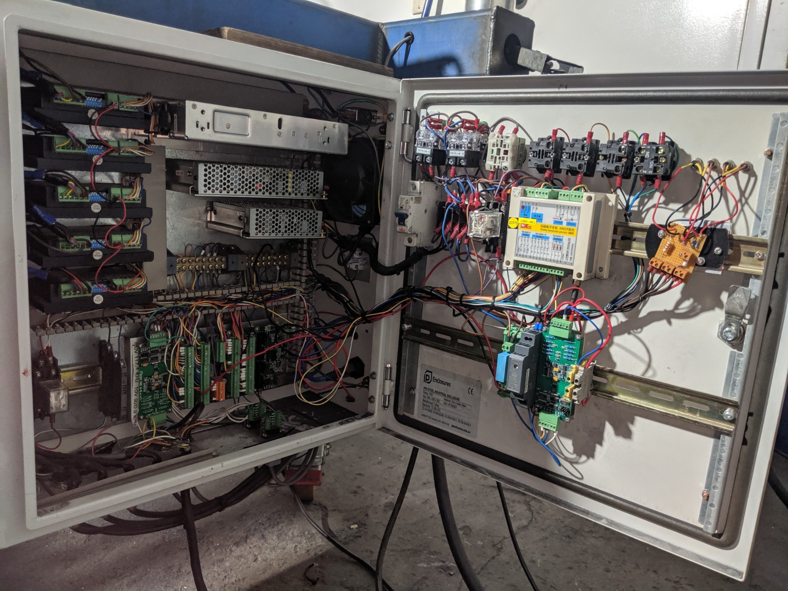
The 48v power runs along the top of the enclosure
The motor leads run down the left side of the enclosure.
For the motor leads, I used 5 terminal sockets so the shield could pass into the enclosure and be grounded right at the driver.
I did this by adding a spade connector to the shield and folding it back and used some heatshrink. If you look closely, you can see blue connectors which take the shield over to a copper earth point.
The unshielded step and direction run up to the right of the controllers (under the one remaining cover)
The motor connectors are on the left bottom. The limit switches are on the right bottom
If I was to add encoders, I would route them with the step and direction and exit at the bottom probably in line with the motor outputs.
If I was to do it again (and another work in progress), I'd use DIN rail everything but still keep the AC power segregated with the motor power supply where the box of terminals are and have the drivers and logic go out the back where the crimpers are.
You will see I used a couple of BUS bars for field power in my current control box but using a Mesa DIN mount Common X2 and their DIN rail mounts makes this much more compact with a 7i96.
You can see where Andy is coming from re power supplies vs DIN rail ones and I have an extra black one there for ohmic sensing. BUt heck what you have will work!
Attachments:
The following user(s) said Thank You: jools
Please Log in or Create an account to join the conversation.
- pl7i92
-
- Offline
- Platinum Member
-
Less
More
- Posts: 1872
- Thank you received: 358
07 Nov 2019 10:24 #149828
by pl7i92
Replied by pl7i92 on topic Does this wiring layout look ok for a starting point?
Rod is the case closable with all the stuff on the door
lots of drivers is this double traction on x and y
lots of drivers is this double traction on x and y
Please Log in or Create an account to join the conversation.
Moderators: PCW, jmelson
Time to create page: 0.189 seconds