Using Siemens PLC modules as Mesa Anything IO
- helioz2000
- Offline
- New Member
-

Less
More
- Posts: 16
- Thank you received: 8
12 Apr 2020 06:02 - 12 Apr 2020 22:24 #163734
by helioz2000
Using Siemens PLC modules as Mesa Anything IO was created by helioz2000
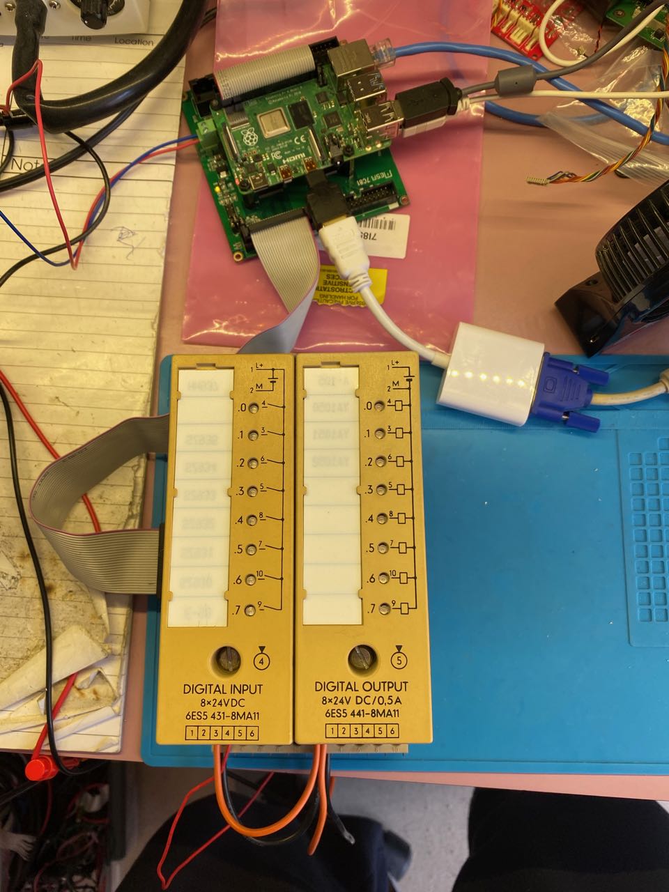
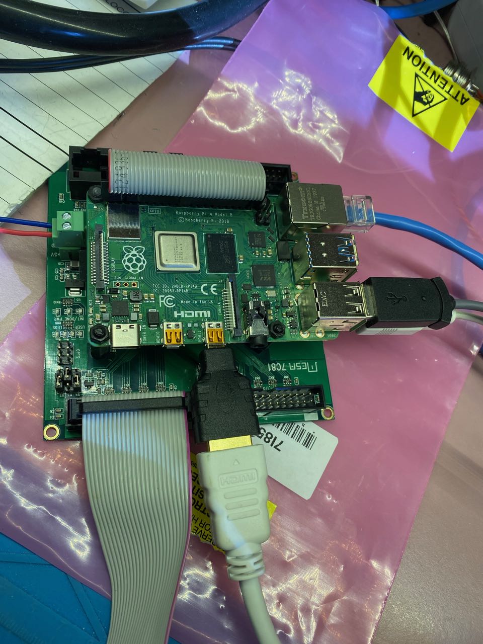
I'm new to LinuxCNC but old to the commercial world of PLC and Automation. After purchasing my first Mesa cards (7C81+7i85S) I had the need to add some digital Inputs and Outputs (Homing switches, etc) to my stepper & encoder interface.
Second hand Siemens PLC modules from the old S5-100U series are available at very reasonable prices (or nix in my case) and offer robust interface circuitry for digital IO. These modules can be adapted to connect to the Mesa anything IO interface and protect the FPGA chip. In my case, the Anything IO interface comes in the format of 25pin D-sub connectors provided via the IDC26 pin header on the 7C81 (and other) cards. However, any fo the Anything IO formats are suitable as long as the pin is reported as GPIO by mesaflash (IOPort None).
I decided to use 1 x 6ES5 431-8MA11 (8xDigIn 24VDC opto isolated) and 1 x 6ES5 441-8MA11 (8x24DC 0.5A Dig Out).
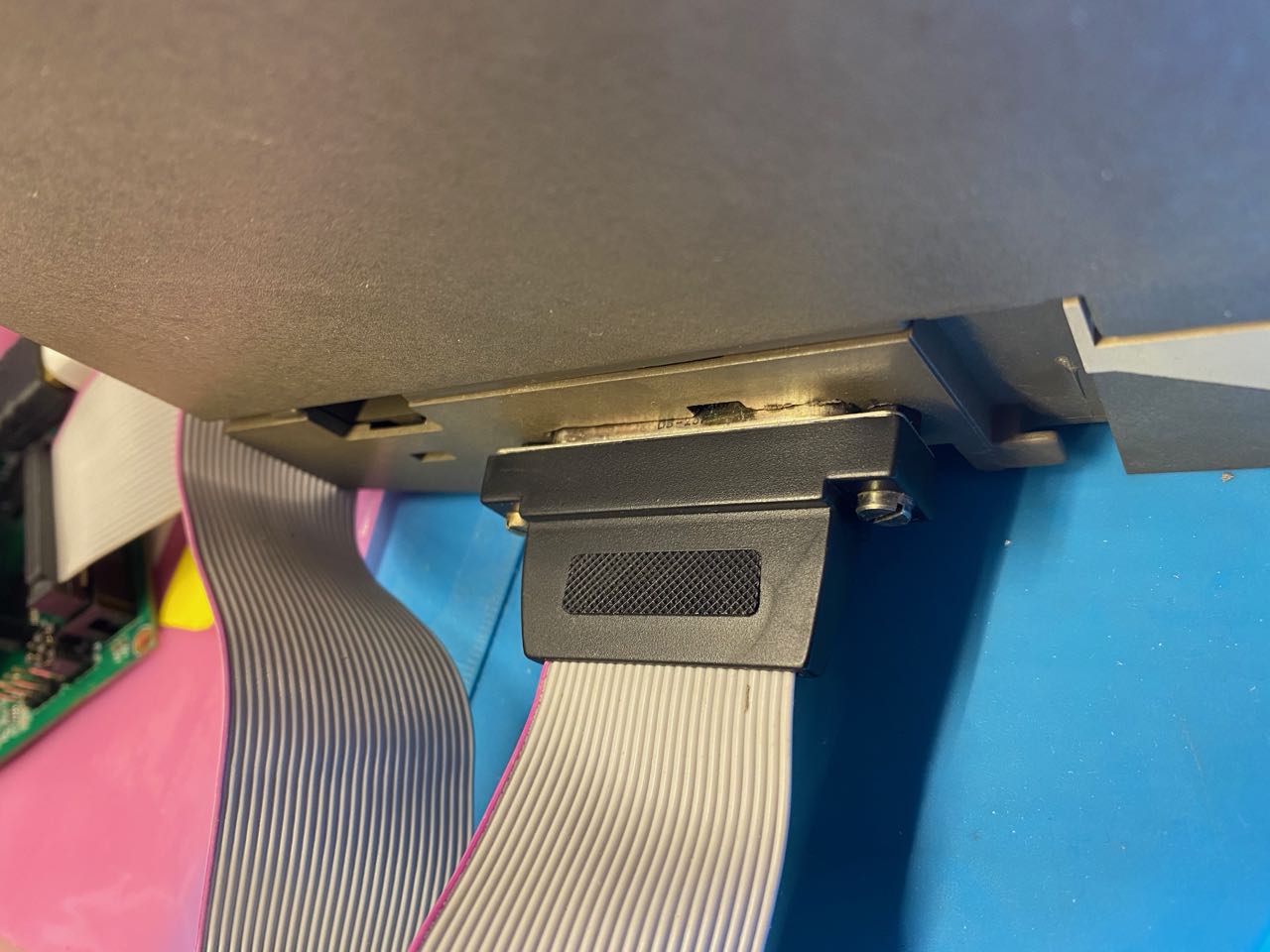
Here are a couple of pics to show the Siemens modules connected to the 7C81 (inc. Raspberry Pi):
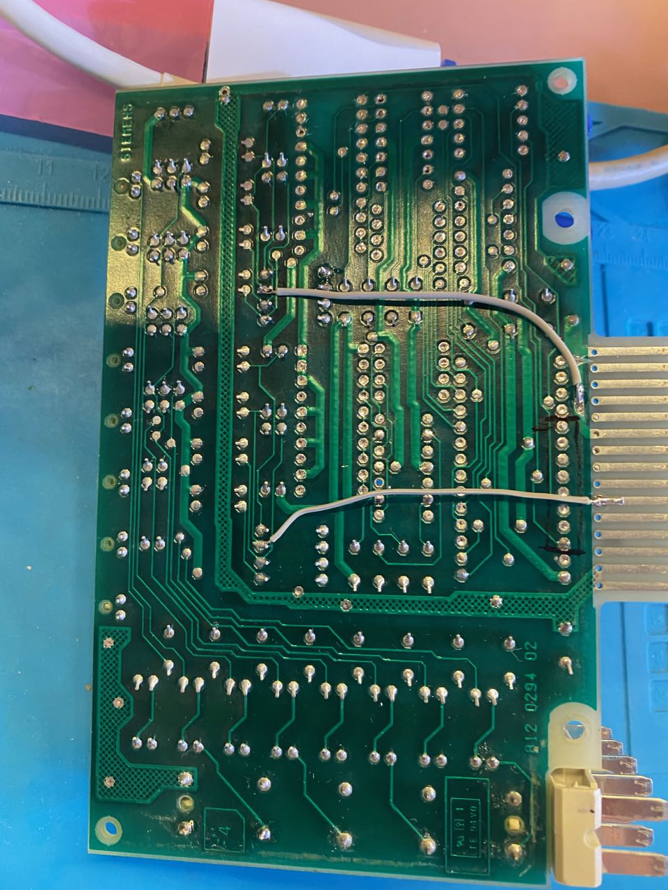
To modify the Siemens Input module I first removed the bus decoder circuit which then leaves only the 24V inputs with opto couplers:
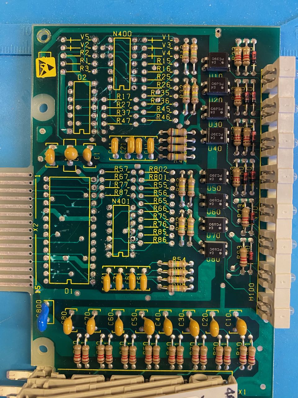
The next step was to decide which pin of the edge connector pins to assign to the anything IO interface. I decided on this layout (from the top of the card):
- 0V
- 5V (supply from anything IO)
- not used
- not used
- IO 0
- IO 1
- IO 2
- IO 3
- IO 4
- IO 5
- IO 6
- IO 7
- not used
- not used
- not used
- not used
The 5V supply pins are the same as used by Siemens so will work with the existing circuit.
The track I was using for IO 6 had to be cut on PCB as it was going to a ground connection.
The last step was to install wire links from the edge connector to the opto coupler outputs, one per IO channel:
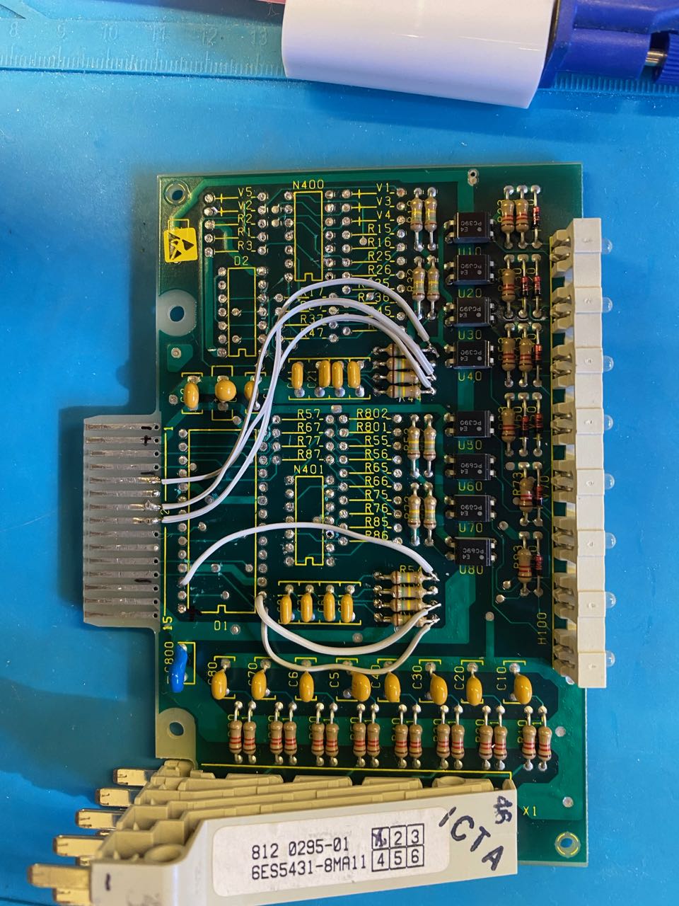
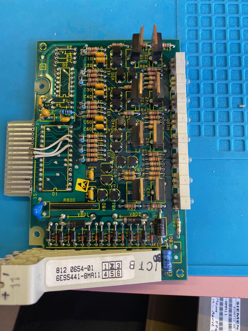
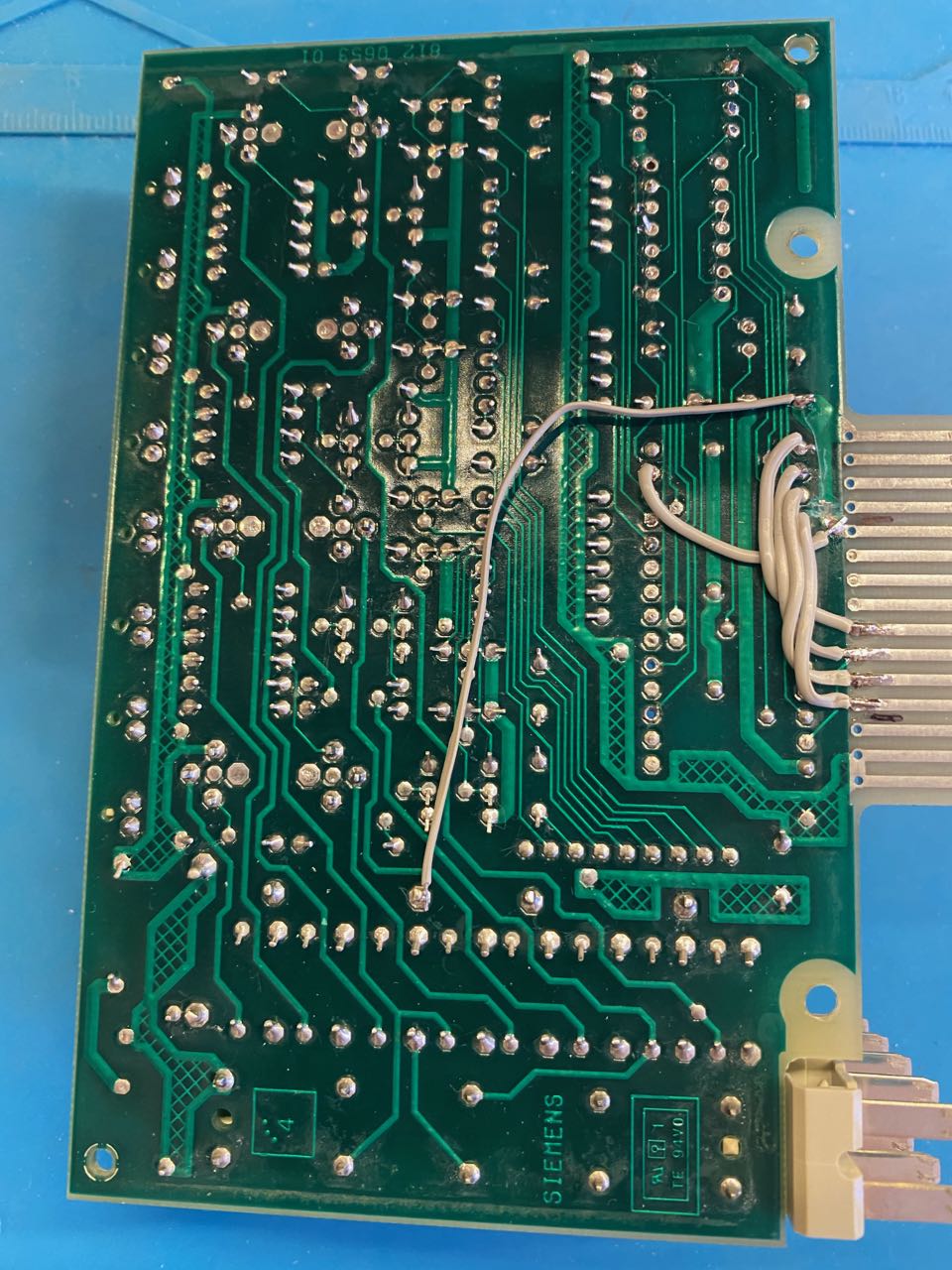
The output module was slightly more challenging.
Bus decoder circuit removed, same track cut as on the input module, Diode V2 replaced with a wire link and a bride from the Anything IO supplied 0V to the external (24VDC) supply negative connection (longest bridge on the bottom of the PCB).
8 x 1K pullup resistors installed (blue resistors shown in photo).
Wire links from the edge connector to the drive input for each output.
That's the conversion of the IO modules, they are now ready to use and can be wired to the anything IO interface.
To facilitate installation I modified a bus module (6ES5 700-8MA11) by removing the bus decoder chip and installing a DB25 connector:
The modified bus module contains the following circuit
IO0-7 to the left edge connector pins
IO8-15 to the right edge connector pins
+5V and 0V to L+R edge connector pins
I hope this post may help someone else to use industrial IO in a home-brew solution.
PS:
For those interested in using S5-100U IO modules without modifying them here is a link to the technical information which explains how the backplane bus and bus decoder chip work:
patents.google.com/patent/EP0235559A1/en
Anyone interested to develop a LinucCNC interface adapter for S5-100U I/O modules?
Second hand Siemens PLC modules from the old S5-100U series are available at very reasonable prices (or nix in my case) and offer robust interface circuitry for digital IO. These modules can be adapted to connect to the Mesa anything IO interface and protect the FPGA chip. In my case, the Anything IO interface comes in the format of 25pin D-sub connectors provided via the IDC26 pin header on the 7C81 (and other) cards. However, any fo the Anything IO formats are suitable as long as the pin is reported as GPIO by mesaflash (IOPort None).
I decided to use 1 x 6ES5 431-8MA11 (8xDigIn 24VDC opto isolated) and 1 x 6ES5 441-8MA11 (8x24DC 0.5A Dig Out).
Here are a couple of pics to show the Siemens modules connected to the 7C81 (inc. Raspberry Pi):
To modify the Siemens Input module I first removed the bus decoder circuit which then leaves only the 24V inputs with opto couplers:
The next step was to decide which pin of the edge connector pins to assign to the anything IO interface. I decided on this layout (from the top of the card):
- 0V
- 5V (supply from anything IO)
- not used
- not used
- IO 0
- IO 1
- IO 2
- IO 3
- IO 4
- IO 5
- IO 6
- IO 7
- not used
- not used
- not used
- not used
The 5V supply pins are the same as used by Siemens so will work with the existing circuit.
The track I was using for IO 6 had to be cut on PCB as it was going to a ground connection.
The last step was to install wire links from the edge connector to the opto coupler outputs, one per IO channel:
The output module was slightly more challenging.
Bus decoder circuit removed, same track cut as on the input module, Diode V2 replaced with a wire link and a bride from the Anything IO supplied 0V to the external (24VDC) supply negative connection (longest bridge on the bottom of the PCB).
8 x 1K pullup resistors installed (blue resistors shown in photo).
Wire links from the edge connector to the drive input for each output.
That's the conversion of the IO modules, they are now ready to use and can be wired to the anything IO interface.
To facilitate installation I modified a bus module (6ES5 700-8MA11) by removing the bus decoder chip and installing a DB25 connector:
The modified bus module contains the following circuit
IO0-7 to the left edge connector pins
IO8-15 to the right edge connector pins
+5V and 0V to L+R edge connector pins
I hope this post may help someone else to use industrial IO in a home-brew solution.
PS:
For those interested in using S5-100U IO modules without modifying them here is a link to the technical information which explains how the backplane bus and bus decoder chip work:
patents.google.com/patent/EP0235559A1/en
Anyone interested to develop a LinucCNC interface adapter for S5-100U I/O modules?
Last edit: 12 Apr 2020 22:24 by helioz2000. Reason: added link to S5-100U bus system info
The following user(s) said Thank You: Mike_Eitel, tommylight
Please Log in or Create an account to join the conversation.
- Mike_Eitel
-

- Offline
- Platinum Member
-

Less
More
- Posts: 1052
- Thank you received: 183
12 Apr 2020 12:45 #163747
by Mike_Eitel
Replied by Mike_Eitel on topic Using Siemens PLC modules as Mesa Anything IO
Congrats
That is a very nice idea. I also have a bunch of them in some dark corners.
Believe i still have several complete sets somewhere. Just use and like the 115U powersupplies.
Mike
That is a very nice idea. I also have a bunch of them in some dark corners.
Believe i still have several complete sets somewhere. Just use and like the 115U powersupplies.
Mike
The following user(s) said Thank You: helioz2000
Please Log in or Create an account to join the conversation.
- tommylight
-

- Offline
- Moderator
-

Less
More
- Posts: 21700
- Thank you received: 7417
12 Apr 2020 15:09 #163768
by tommylight
Replied by tommylight on topic Using Siemens PLC modules as Mesa Anything IO
Nicely done !
The following user(s) said Thank You: helioz2000
Please Log in or Create an account to join the conversation.
Moderators: PCW, jmelson
Time to create page: 0.381 seconds