Mesa StepGen ouputs with Yaskawa servos
- johnbl
- Offline
- Senior Member
-

Less
More
- Posts: 42
- Thank you received: 5
14 Apr 2020 11:47 #163937
by johnbl
Mesa StepGen ouputs with Yaskawa servos was created by johnbl
Hi,
I would like to drive my Yaskawa servos with step/dir differential outputs from a 7i96, and found this in the servo's manual:
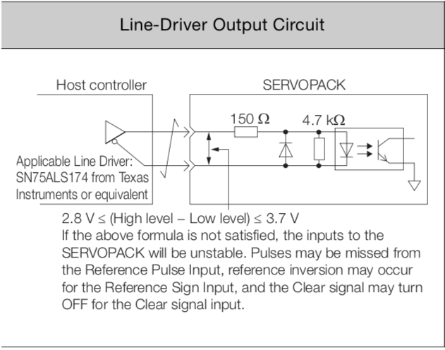
Does that mean that the differential output voltage should be 3.3V instead of the 5V from the 7i96?
I would like to drive my Yaskawa servos with step/dir differential outputs from a 7i96, and found this in the servo's manual:
Does that mean that the differential output voltage should be 3.3V instead of the 5V from the 7i96?
Please Log in or Create an account to join the conversation.
- bbsr_5a
- Offline
- Platinum Member
-

Less
More
- Posts: 544
- Thank you received: 106
14 Apr 2020 11:55 #163940
by bbsr_5a
Replied by bbsr_5a on topic Mesa StepGen ouputs with Yaskawa servos
the servopack shout accept the 5V as it is standard the SN is only for controls that work on 24V signaling
please give the correct yaskawa drive number to confirm the input
please give the correct yaskawa drive number to confirm the input
Please Log in or Create an account to join the conversation.
- PCW
-

- Away
- Moderator
-

Less
More
- Posts: 17996
- Thank you received: 5282
14 Apr 2020 12:45 - 14 Apr 2020 12:58 #163942
by PCW
Replied by PCW on topic Mesa StepGen ouputs with Yaskawa servos
With the input circuitry shown, the Opto LED current will be roughly 12 to 18 mA.
adding a ~120 ohm series resistor will get you in the middle of that range with 5V drive.
(and 75 to 180 ohms should work)
adding a ~120 ohm series resistor will get you in the middle of that range with 5V drive.
(and 75 to 180 ohms should work)
Last edit: 14 Apr 2020 12:58 by PCW.
The following user(s) said Thank You: johnbl
Please Log in or Create an account to join the conversation.
- johnbl
- Offline
- Senior Member
-
Less
More
- Posts: 42
- Thank you received: 5
14 Apr 2020 12:46 - 14 Apr 2020 13:02 #163943
by johnbl
Replied by johnbl on topic Mesa StepGen ouputs with Yaskawa servos
It's a SGD7S servopack.
Thanks PCW. Too bad an extra resistor is needed.
Thanks PCW. Too bad an extra resistor is needed.
Last edit: 14 Apr 2020 13:02 by johnbl.
Please Log in or Create an account to join the conversation.
- johnbl
- Offline
- Senior Member
-
Less
More
- Posts: 42
- Thank you received: 5
28 Aug 2020 15:23 - 28 Aug 2020 15:23 #179849
by johnbl
Replied by johnbl on topic Mesa StepGen ouputs with Yaskawa servos
Does this also apply to the 7i85S differential outputs? It looks like it uses different drivers.With the input circuitry shown, the Opto LED current will be roughly 12 to 18 mA.
adding a ~120 ohm series resistor will get you in the middle of that range with 5V drive.
(and 75 to 180 ohms should work)
Last edit: 28 Aug 2020 15:23 by johnbl.
Please Log in or Create an account to join the conversation.
- PCW
-
- Away
- Moderator
-
Less
More
- Posts: 17996
- Thank you received: 5282
28 Aug 2020 15:35 - 28 Aug 2020 15:36 #179851
by PCW
Replied by PCW on topic Mesa StepGen ouputs with Yaskawa servos
Yes, all Mesa daughter card step/dir differential outputs have 5V swings
Last edit: 28 Aug 2020 15:36 by PCW.
Please Log in or Create an account to join the conversation.
- johnbl
- Offline
- Senior Member
-
Less
More
- Posts: 42
- Thank you received: 5
18 Nov 2021 15:02 #226876
by johnbl
Replied by johnbl on topic Mesa StepGen ouputs with Yaskawa servos
So I've been finally able to connect my Yaskawa servos to my 7i85s but I'm getting mixed results: it seems like the pulse train is not reliable and sometimes the servo drive does not recognize the pulses.
After taking a closer look at the 7i85s and assuming I can read correctly the datasheet of the ISL32174E used as differential driver, the diff. output voltage is not 5V but more like 4V. Not a huge issue, with a 120R series resistor there should still be about 10mA flowing through the opto-LED.
However I also noticed that the step/dir outputs from the fpga are terminated with a Thevenin termination (220R pullup to 3.3V and 470R pulldown to ground), which brings the voltage down to about 2.3V.
As per the ISL3217 datasheet, this is below the minimum 2.7V required for a logic HIGH.
Could this be the issue or am I wide of the mark?
Please Log in or Create an account to join the conversation.
- PCW
-
- Away
- Moderator
-
Less
More
- Posts: 17996
- Thank you received: 5282
18 Nov 2021 15:28 #226879
by PCW
Replied by PCW on topic Mesa StepGen ouputs with Yaskawa servos
The open circuit voltage of the terminator will be close to 2.3V but driven high ,
it will be closer to 2.7 or 2.8V (and about .4V when driven low) I don't think this is an
issue. What step length are you using? I would always start with at least 2X the drives
minimum step length value.
it will be closer to 2.7 or 2.8V (and about .4V when driven low) I don't think this is an
issue. What step length are you using? I would always start with at least 2X the drives
minimum step length value.
Please Log in or Create an account to join the conversation.
- johnbl
- Offline
- Senior Member
-
Less
More
- Posts: 42
- Thank you received: 5
18 Nov 2021 15:34 #226880
by johnbl
Replied by johnbl on topic Mesa StepGen ouputs with Yaskawa servos
Right, I can indeed measure about 2.8V. Still, this seems way too close to the minimum threshold.
I'm currently using 1us wide pulses for steps and 5us for dir, which is well within spec:
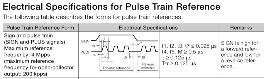
I'm currently using 1us wide pulses for steps and 5us for dir, which is well within spec:
Attachments:
Please Log in or Create an account to join the conversation.
- PCW
-
- Away
- Moderator
-
Less
More
- Posts: 17996
- Thank you received: 5282
18 Nov 2021 15:58 - 18 Nov 2021 16:03 #226884
by PCW
Replied by PCW on topic Mesa StepGen ouputs with Yaskawa servos
2.8V is a legal high (the actual input thresholds are about 1.7V)
Its also about the best you can do into termination with 3.3V drive.
Note that the minimum VIH and VIL specifications are not the
input threshold values but the minimum high and low levels to
guarantee sufficient noise margin (typically 1.0V for TTL interface
levels like these)
As an experiment, you can get a bit higher drive by setting the
FPGA card I/O to 3.3V tolerant mode which reduces the output
resistance, but this is not the issue, its something else.
Last edit: 18 Nov 2021 16:03 by PCW.
The following user(s) said Thank You: johnbl
Please Log in or Create an account to join the conversation.
Moderators: PCW, jmelson
Time to create page: 0.441 seconds