Spindle Control with Mesa and DMM DYN4
- travis1581
- Offline
- New Member
-

Less
More
- Posts: 4
- Thank you received: 1
29 Aug 2020 16:50 #179945
by travis1581
Spindle Control with Mesa and DMM DYN4 was created by travis1581
I recently wired up a power box for a DMM AC servo that I intend to use as a spindle motor. The motor works as it should when I control it via Windows and the DMM software. Now its time to wire it up for linuxCNC control. I was hoping I could get someone to double check me before I wired everything up.
DYN4 Manual: www.dmm-tech.com/Files/DYN4MS-ZM7-A10A.pdf
Page 11 is where the pin descriptions start
I am wiring to a 7i76 and only need to the spindle to rotate in one direction (ie. I will not be ridgid tapping) and do not have a brake on the motor. I have a DB29 BoB and plan on using the wiring attached. Does this look right? Is there anything I am missing?
Please Log in or Create an account to join the conversation.
- PCW
-

- Offline
- Moderator
-

Less
More
- Posts: 17940
- Thank you received: 5255
29 Aug 2020 17:21 #179946
by PCW
Replied by PCW on topic Spindle Control with Mesa and DMM DYN4
7I76 TB4
1 SPINDLE-     --> JP4 25
2 SPINDLE OUT  --> JP4 13
3 SPINDLE+     --> +10 or +12V
4 NC
5 SPINDLE ENA- --> JP4 15
6 SPINDLE ENA+ --> +24V
7 SPINDLE DIR-
8 SPINDLE DIR+
The following user(s) said Thank You: travis1581
Please Log in or Create an account to join the conversation.
- JohnnyCNC
-

- Offline
- Platinum Member
-

Less
More
- Posts: 570
- Thank you received: 111
29 Aug 2020 18:06 #179951
by JohnnyCNC
Replied by JohnnyCNC on topic Spindle Control with Mesa and DMM DYN4
PCW to the rescue on your question.
Not required but I would also connect the JP5 encoder output so that LCNC can tell when the spindle has reached the commanded speed and then commence motion. If you are geared 1:1 with the spindle it is an easy hookup to the encoder input on TB3.
Not required but I would also connect the JP5 encoder output so that LCNC can tell when the spindle has reached the commanded speed and then commence motion. If you are geared 1:1 with the spindle it is an easy hookup to the encoder input on TB3.
Please Log in or Create an account to join the conversation.
- BeagleBrainz
-

- Visitor
-

29 Aug 2020 19:29 #179960
by BeagleBrainz
Replied by BeagleBrainz on topic Spindle Control with Mesa and DMM DYN4
This is a great thread as I’m connecting up the same kit.
Please Log in or Create an account to join the conversation.
- JohnnyCNC
-
- Offline
- Platinum Member
-
Less
More
- Posts: 570
- Thank you received: 111
29 Aug 2020 19:38 #179961
by JohnnyCNC
Replied by JohnnyCNC on topic Spindle Control with Mesa and DMM DYN4
I'm using a 7i83 for +- 0~10 control. Are you gearing at 1:1 to the spindle? If not I have a circuit that I know works using a slot type opto-sensor.
Please Log in or Create an account to join the conversation.
- travis1581
- Offline
- New Member
-
Less
More
- Posts: 4
- Thank you received: 1
29 Aug 2020 22:19 #179975
by travis1581
I plan on using a 2:1 ratio. I havent thought of the implications here since I only have an encoder on the motor, not the spindle.
Replied by travis1581 on topic Spindle Control with Mesa and DMM DYN4
I'm using a 7i83 for +- 0~10 control. Are you gearing at 1:1 to the spindle? If not I have a circuit that I know works using a slot type opto-sensor.
I plan on using a 2:1 ratio. I havent thought of the implications here since I only have an encoder on the motor, not the spindle.
Please Log in or Create an account to join the conversation.
- JohnnyCNC
-
- Offline
- Platinum Member
-
Less
More
- Posts: 570
- Thank you received: 111
29 Aug 2020 23:48 #179983
by JohnnyCNC
Replied by JohnnyCNC on topic Spindle Control with Mesa and DMM DYN4
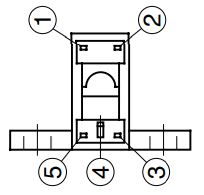
Since you are gearing the motor other than 1:1 you need the index pulse (Z signal) to come from the spindle at 1 pulse per revolution. The A&B signals will come from the encoder output of the DYN4 drive. This is what I did using the following parts:
220 ohm resistor
Sharp Microelectronics GP1A51HRJ00F
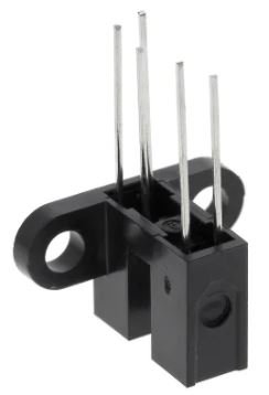
GP1A51HRJ00F to Mesa 7i76
Pin 1 220 ohm resistor to pin 3
Pin 2 & 5 to TB3-15 (GND)
Pin 3 to TB3-12 (+5VP)
Pin 4 to TB3-13 (IDX+)
This is the pin layout looking at the back of the sensor.
This is what the install looks like on my machine.
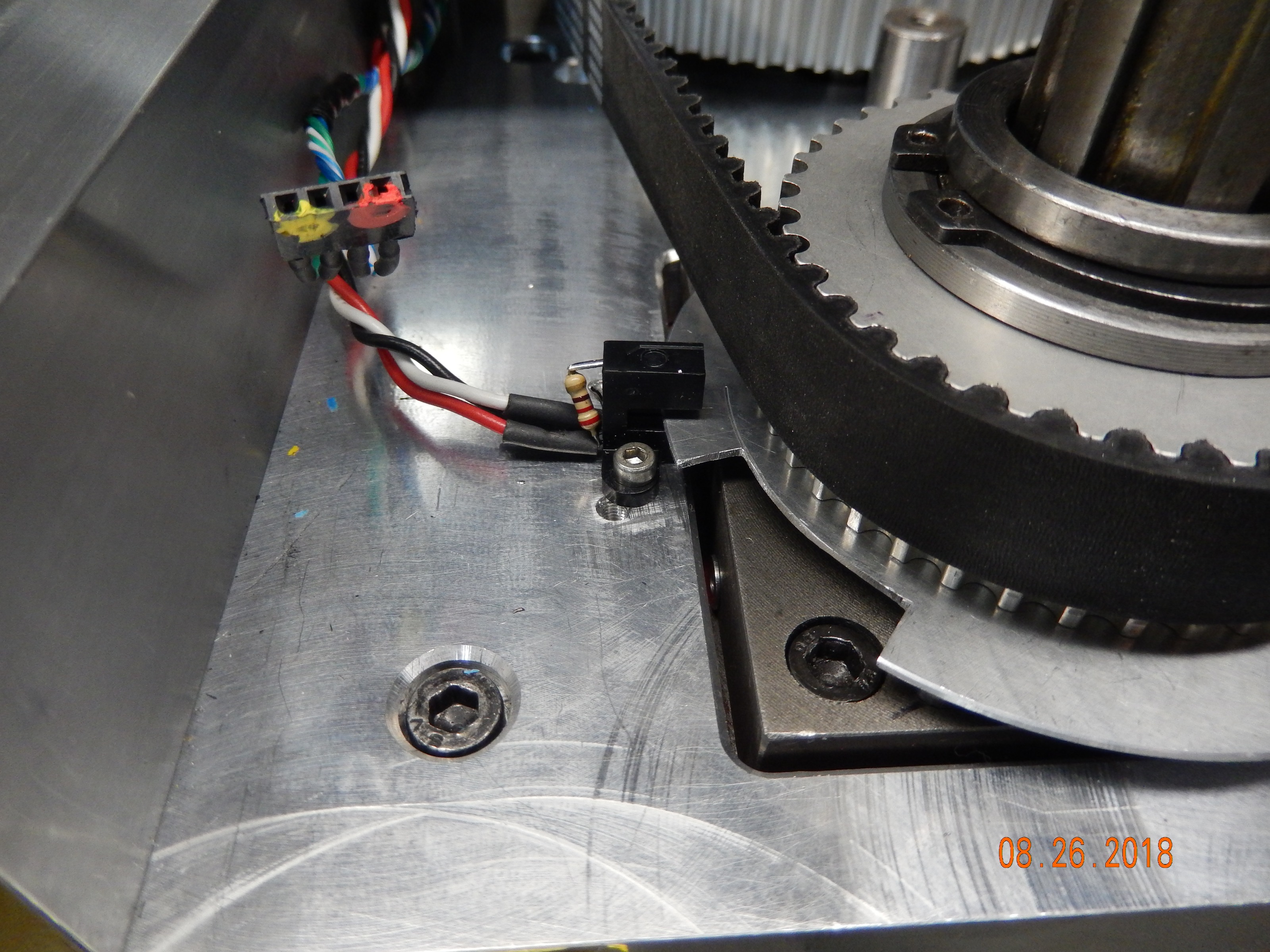
If you happen to see other pictures of my machine that shows two of these mounted on the spindle the second one feeds the RPM display of the DRO I have on my mill.
220 ohm resistor
Sharp Microelectronics GP1A51HRJ00F
GP1A51HRJ00F to Mesa 7i76
Pin 1 220 ohm resistor to pin 3
Pin 2 & 5 to TB3-15 (GND)
Pin 3 to TB3-12 (+5VP)
Pin 4 to TB3-13 (IDX+)
This is the pin layout looking at the back of the sensor.
This is what the install looks like on my machine.
If you happen to see other pictures of my machine that shows two of these mounted on the spindle the second one feeds the RPM display of the DRO I have on my mill.
The following user(s) said Thank You: Clive S, BeagleBrainz
Please Log in or Create an account to join the conversation.
- Clive S
- Offline
- Platinum Member
-
Less
More
- Posts: 2204
- Thank you received: 486
18 Nov 2020 16:49 #189693
by Clive S
Replied by Clive S on topic Spindle Control with Mesa and DMM DYN4
Yes. I have done it that way on several machines but always had the ZAB from the same slotted disc but was not sure about the servo not being in direct sync with the Z sensor
Please Log in or Create an account to join the conversation.
Moderators: PCW, jmelson
Time to create page: 0.215 seconds