Linumeric-LPT V3 - Ethernet to LPT controller for LinuxCNC
- drzasiek90
-
 Topic Author
- Visitor
-

17 Dec 2023 18:35 #288435
by drzasiek90
Linumeric-LPT V3 - Ethernet to LPT controller for LinuxCNC was created by drzasiek90
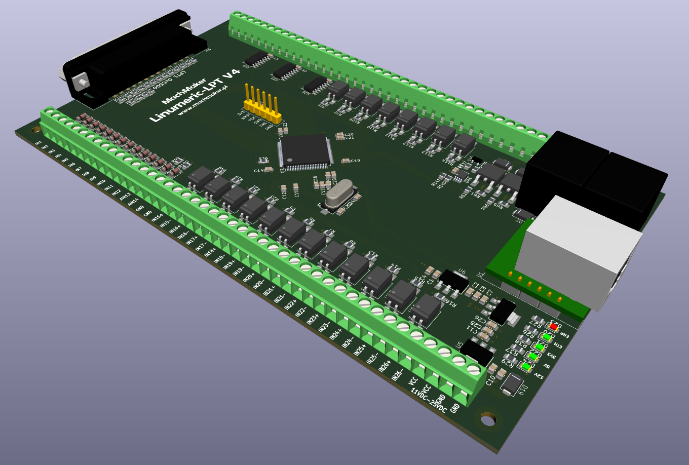
Hi. I would like to show you a device I built. It's called Linumeric-LPT V3 and it's an Ethernet-LPT adapter/controller for linuxCNC. The device works similarly to Linumeric-LPT V1 and V2, only instead of communicating via USB, it communicates via LPT. Reduced delays, increased time determinism. The device is even suitable for controlling a CNC lathe and performing synchronous movements. More details on my website:
www.machmaker.pl/linumeric-lpt-v3
www.machmaker.pl/linumeric-lpt-v3
Please Log in or Create an account to join the conversation.
- tommylight
-

- Away
- Moderator
-

Less
More
- Posts: 21686
- Thank you received: 7411
18 Dec 2023 02:16 #288449
by tommylight
Replied by tommylight on topic Linumeric-LPT V3 - Ethernet to LPT controller for LinuxCNC
Some of us already know, we had some discussions about it but can no find the topic.
Looks nice, it should also work, but i really do not like you not posting the prices, again.
I do like that you have pictures of it's insides, though, utmost respect for that.
Looks nice, it should also work, but i really do not like you not posting the prices, again.
I do like that you have pictures of it's insides, though, utmost respect for that.
Please Log in or Create an account to join the conversation.
- drzasiek90
-
Topic Author
- Visitor
-
18 Dec 2023 07:35 #288467
by drzasiek90
Replied by drzasiek90 on topic Linumeric-LPT V3 - Ethernet to LPT controller for LinuxCNC
Prices will not be a secret. I am preparing an online store on my website, there will be products with given prices. The store opens in January.
I looked through the topics on this forum regarding linumeric - I want to clarify that this device should not be compared to mesa cards. This device works completely differently, it is an LPT port and all control is still done in LinuxCNC on the base thread. The device should be treated as an LPT port with all its advantages and disadvantages.
I looked through the topics on this forum regarding linumeric - I want to clarify that this device should not be compared to mesa cards. This device works completely differently, it is an LPT port and all control is still done in LinuxCNC on the base thread. The device should be treated as an LPT port with all its advantages and disadvantages.
Please Log in or Create an account to join the conversation.
- romanetz
- Offline
- Senior Member
-

Less
More
- Posts: 47
- Thank you received: 34
18 Dec 2023 14:22 - 18 Dec 2023 15:30 #288489
by romanetz
Replied by romanetz on topic Linumeric-LPT V3 - Ethernet to LPT controller for LinuxCNC
I'm really very much interested how you achieved 100 kHz speed over Ethernet, it requires round-trip-time over network less than 10 microseconds. From the description, I made a (erratic) conclusion that any arbitrary sequence could be output with 100 kHz frequency, that yields even a better value, 5 microsecond maximum.
Last edit: 18 Dec 2023 15:30 by romanetz.
Please Log in or Create an account to join the conversation.
- drzasiek90
-
Topic Author
- Visitor
-
18 Dec 2023 17:08 - 18 Dec 2023 17:26 #288493
by drzasiek90
Replied by drzasiek90 on topic Linumeric-LPT V3 - Ethernet to LPT controller for LinuxCNC
It is crucial to comprehend the functioning of this device. This device does not impair the functionality of LinuxCNC; it serves solely as a parallel interface communicating via Ethernet. All control occurs within the computer, akin to the conventional LPT port. The maximum signal frequency supported by the controller is 100 kHz, implying that the base thread in LinuxCNC must operate at this frequency. Personally, I lack a computer capable of handling this frequency due to jitter, and I also lack a machine necessitating such capabilities. I own a laser plotter, two trailing knife plotters, a large milling plotter, and a 3-axis milling machine, none of which require anything beyond the capabilities of a linumeric device to operate. Although all control is buffered, the buffer is limited to the essential minimum. The total loop delay is calculated in real time and is accessible as a signal in the hall.
On my laptops, I can achieve a delay below 1 ms, which is roughly equivalent to the (typical) period of the servo thread. While any delay is not ideal, it can be quantified. If the delay doesn't introduce a significant error, it is deemed acceptable. Take, for instance, homing, material, or tool measurement. Sampling is initially done coarsely and then refined at low speed. Assuming an approach speed to the limit switch of 100 mm/min, a 1 ms delay results in a measurement error of about 1 μm. This error exceeds the expectations and accuracy of most amateur or even semi-amateur machines.In the case of threading, this delay is crucial only for rigid threading, not for regular threading. For example, when cutting a rigid thread with a pitch of 2 mm at a rotational speed of 300 rpm, a 1 ms delay yields a thread position error of approximately 0.01 mm in both directions. I believe that, for a significant number of users, this error is smaller than the accuracy of their machine and is deemed acceptable.I am transparent about the advantages and disadvantages of this solution, and I don't withhold any information. Regarding communication via Ethernet, I have created a special distribution of Debian 12 that comes with everything installed to support linumeric-LPT V1/V2/V3, and the system is optimized for Ethernet communication. You can run the system in live mode, and everything functions immediately.
On my laptops, I can achieve a delay below 1 ms, which is roughly equivalent to the (typical) period of the servo thread. While any delay is not ideal, it can be quantified. If the delay doesn't introduce a significant error, it is deemed acceptable. Take, for instance, homing, material, or tool measurement. Sampling is initially done coarsely and then refined at low speed. Assuming an approach speed to the limit switch of 100 mm/min, a 1 ms delay results in a measurement error of about 1 μm. This error exceeds the expectations and accuracy of most amateur or even semi-amateur machines.In the case of threading, this delay is crucial only for rigid threading, not for regular threading. For example, when cutting a rigid thread with a pitch of 2 mm at a rotational speed of 300 rpm, a 1 ms delay yields a thread position error of approximately 0.01 mm in both directions. I believe that, for a significant number of users, this error is smaller than the accuracy of their machine and is deemed acceptable.I am transparent about the advantages and disadvantages of this solution, and I don't withhold any information. Regarding communication via Ethernet, I have created a special distribution of Debian 12 that comes with everything installed to support linumeric-LPT V1/V2/V3, and the system is optimized for Ethernet communication. You can run the system in live mode, and everything functions immediately.
Attachments:
Last edit: 18 Dec 2023 17:26 by drzasiek90.
Please Log in or Create an account to join the conversation.
- romanetz
- Offline
- Senior Member
-
Less
More
- Posts: 47
- Thank you received: 34
18 Dec 2023 18:04 - 18 Dec 2023 18:08 #288502
by romanetz
Replied by romanetz on topic Linumeric-LPT V3 - Ethernet to LPT controller for LinuxCNC
Does it mean that Linumeric-LPT receives every 1 ms a packet from PC that is enough to output some number of bits with 5 us resolution? Thus, 1ms/5us=200 samples, multiply by number of bits in LPT, say, 16, yields 1ms/5us*16bits/8bits per byte=400 bytes every period? (litexcnc yet hasn't fifo mode but there are some examples of udp stream receiver in litex to provide control for something like laser galvanic scanner - and there is the same obvious application for Linumeric-LPT too)
Last edit: 18 Dec 2023 18:08 by romanetz.
Please Log in or Create an account to join the conversation.
- drzasiek90
-
Topic Author
- Visitor
-
18 Dec 2023 19:31 #288507
by drzasiek90
Replied by drzasiek90 on topic Linumeric-LPT V3 - Ethernet to LPT controller for LinuxCNC
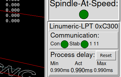
This time results from communication time, module service time, buffering time, base period, etc. The device is made of very simple and easily accessible modules, so you can build it yourself without specialized tools and skills. About 1 ms is the total delay time that I can achieve on my laptop - my configuration has a base period of 30 us - no more is needed, and my computer cannot do much more (the computer is not specially selected; it is already an old average). The delay is counted in read-write communication, i.e., it is the propagation time of data in the input-output FIFO buffers. 100 kHz gives 10us, not 5us. Theoretically, every 10us, it is possible to change the signal, which does not mean that 1 ms is buffered. In my case, the buffer time is currently 240us input and 240us output, which, with a base period of 30us, gives 8 samples in the FIFO input buffer and 8 in the FIFO output buffer. The remaining delay time results from network communication, communication support via the uC, and the W5500 module - as I wrote, these are very simple modules and have some limitations. Most of us, when using the LPT port, focus on the base period, and the servo period leaves the default of 1 ms (I think). In my opinion, this is an incorrect approach, and the servo period should also be minimized (at least 2 times the base period), so we should have a modern, efficient computer for LinuxCNC. For example, we can measure on an oscilloscope what the delay will be between reading and writing on the physical port LPT 0x378 with a servo period of 1 ms. We will connect the input as a limit signal (blue graph) and the output as an amplifier enable signal (yellow graph).
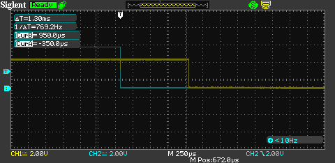
It turns out that the delay varies up to 1 ms because the servo thread manages the response. This is also crucial in threading, as the servo thread determines the start of the cycle. If we minimize the servo period (in my case, 30us base and 90us servo), the delay tested in the same way may yield a similar result on Linumeric-LPT V3.
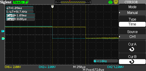
The conclusion is that with proper and accurate configuration of Linumeric-LPT V3, the results will be better than with the standard 'ill-thought-out' configuration of the physical LPT port.
It turns out that the delay varies up to 1 ms because the servo thread manages the response. This is also crucial in threading, as the servo thread determines the start of the cycle. If we minimize the servo period (in my case, 30us base and 90us servo), the delay tested in the same way may yield a similar result on Linumeric-LPT V3.
The conclusion is that with proper and accurate configuration of Linumeric-LPT V3, the results will be better than with the standard 'ill-thought-out' configuration of the physical LPT port.
Attachments:
Please Log in or Create an account to join the conversation.
- cakeslob
- Offline
- Platinum Member
-

Less
More
- Posts: 926
- Thank you received: 278
24 Dec 2023 00:24 #288958
by cakeslob
Replied by cakeslob on topic Linumeric-LPT V3 - Ethernet to LPT controller for LinuxCNC
Hey this looks pretty cool. I was just working on my own remora version using the 411, then stumbled on this. Ive been keeping my eye on your other project for a while though. Mine includes a raspberry pi header.
I am very interested to see your firmware and linuxcnc driver.
I am very interested to see your firmware and linuxcnc driver.
Please Log in or Create an account to join the conversation.
- drzasiek90
-
Topic Author
- Visitor
-
24 Dec 2023 19:38 #289012
by drzasiek90
Replied by drzasiek90 on topic Linumeric-LPT V3 - Ethernet to LPT controller for LinuxCNC
LPT is really sufficient to run most machines. All this can be divided really sensibly in such a way that the number of pins in the LPT is sufficient and the frequency of service is also sufficient. However, I am planning a fourth version of the device which, in addition to the LPT port, will include industrial standard inputs/outputs, also isolated, relay outputs, high-current outputs, and analog inputs and outputs. I already have a ready PCB design.
Attachments:
Please Log in or Create an account to join the conversation.
- TOLP2
- Offline
- Elite Member
-

Less
More
- Posts: 225
- Thank you received: 178
29 Dec 2023 22:21 #289337
by TOLP2
Replied by TOLP2 on topic Linumeric-LPT V3 - Ethernet to LPT controller for LinuxCNC
Don;t want to hijack the topic about another product. But could you elaborate more about the FIFO mode you described? Do you mean that the card should buffer more frames?Does it mean that Linumeric-LPT receives every 1 ms a packet from PC that is enough to output some number of bits with 5 us resolution? Thus, 1ms/5us=200 samples, multiply by number of bits in LPT, say, 16, yields 1ms/5us*16bits/8bits per byte=400 bytes every period? (litexcnc yet hasn't fifo mode but there are some examples of udp stream receiver in litex to provide control for something like laser galvanic scanner - and there is the same obvious application for Linumeric-LPT too)
Please Log in or Create an account to join the conversation.
Moderators: PCW, jmelson
Time to create page: 0.686 seconds