Using a 7i92t as replacement for a parallel port

More
1 year 3 months ago - 1 year 3 months ago #331908 by Cerezas
Thank you unknown, that's very important information. I noticed that the card came with the W1 and W2 jumpers in pull-up mode. I moved them to pull-downs. 
Hardware-wise, I'm closer to my goal. 

Now, regarding software configuration. I used pncconf to generate a configuration using 7i92t_g540d.bin, since pncconf does not show the firmware that corresponds to what I need (in the stepconfs, dir and step are swapped). The firmware that matches the lathe is 7i92t_benezanx2d.bin.

Can anyone review my hal and ini files (attached) and tell me how to handle swapping the dir and step pins? After the hal is corrected, I assume I need to flash the benezan firmware, right?

Also, if someone can suggest how to clean up those files... I only need to control the pins I mentioned when I opened this topic (see top).

I may need to come back later about the PID stuff and the scale calculation. One of the issues I found in pncconfig is that the pitch can only be a value >= 1, I needed to enter a value of 0.8 mm/rev.
Last edit: 1 year 3 months ago by Cerezas.

Please Log in or Create an account to join the conversation.
More
1 year 3 months ago #331909 by PCW
Look like the scaling is wrong on the X Axis ( max velocity is .1666 mm/s )

If there is an issue with pncconfs scaling helper, you could just calculate
the steps per mm and enter that directly.

The PID boilerplate is fine.

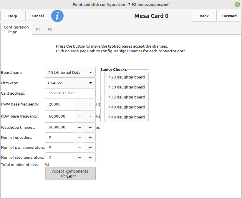
To setup pin 16 for spindle control you need to set the number of stepgens to
3 or 2 in pncconf to free up pin 16 as GPIO 5. I would also set the number of pwmgens
and encoders to 0, then hit "Accept components changes" to free up all GPIO
for any other outputs or inputs you need:


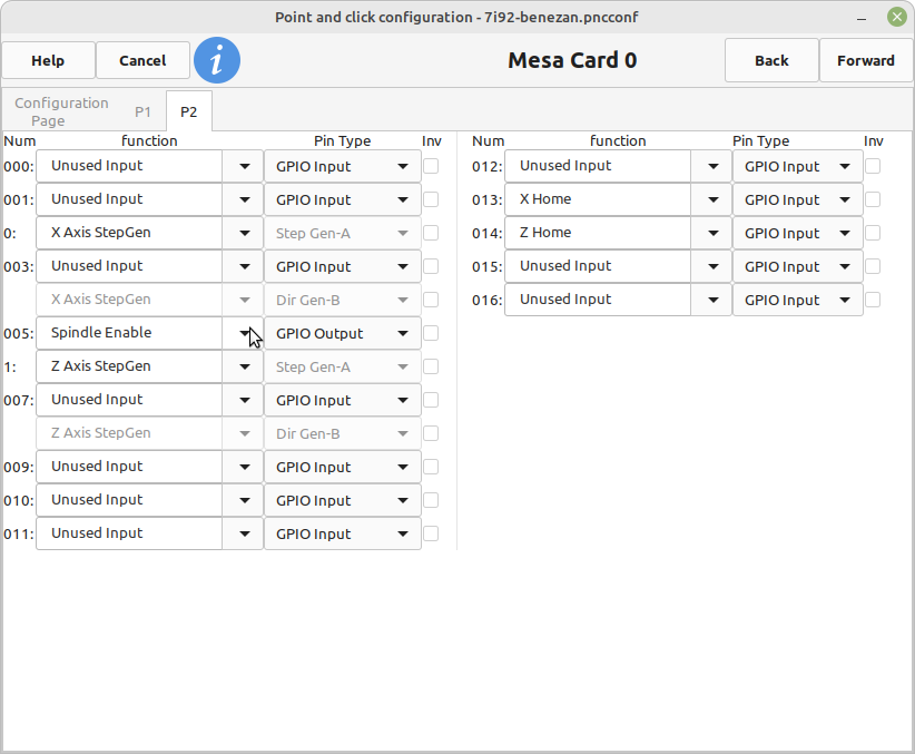
GPIO outputs need to be set to "GPIO Output" in the pin type menu:


Please Log in or Create an account to join the conversation.
More
1 year 3 months ago - 1 year 3 months ago #331915 by Cerezas
Strange. I'm attaching the pncconf file that generated the HAL and INI I posted before. When I load it, I see different screens from what you are showing. I had already set pwms and encoders to 0 and steppers to 2.

Anyway, the question remains: how do I change pin 2 (002)  to be XDIR, pin 3 (004) to be XSTEP (Inverted), pin 4 (006) to be ZDIR and pin 5 (008) to be ZSTEP (Inverted)? I was thinking this needs to be done in the HAL file, but I don't see how.
 
Last edit: 1 year 3 months ago by Cerezas.

Please Log in or Create an account to join the conversation.

More
1 year 3 months ago - 1 year 3 months ago #331916 by PCW
I think there's a misunderstanding...

You don't need to change any pins.

If you use 7i92t_benezanx2d.bin firmware, the pins are
already correct:

Code:
IO Connections for P2 DB25 pin#             I/O   Pri. func    Sec. func        Chan     Sec. Pin func   Sec. Pin Dir  1                      0   IOPort       None            14                      1   IOPort       None             2                      2   IOPort       StepGen          0        Dir/Table2      (Out) 15                      3   IOPort       None             3                      4   IOPort       StepGen          0        Step/Table1     (Out) 16                      5   IOPort       StepGen          4        Step/Table1     (Out)  4                      6   IOPort       StepGen          1        Dir/Table2      (Out) 17                      7   IOPort       PWM              0        PWM             (Out)  5                      8   IOPort       StepGen          1        Step/Table1     (Out)  6                      9   IOPort       StepGen          2        Dir/Table2      (Out)  7                     10   IOPort       StepGen          2        Step/Table1     (Out)  8                     11   IOPort       StepGen          3        Dir/Table2      (Out)  9                     12   IOPort       StepGen          3        Step/Table1     (Out) 10                     13   IOPort       None            11                     14   IOPort       QCount           0        Quad-A          (In) 12                     15   IOPort       QCount           0        Quad-B          (In) 13                     16   IOPort       QCount           0        Quad-IDX        (In)  
Last edit: 1 year 3 months ago by PCW.

Please Log in or Create an account to join the conversation.

More
1 year 3 months ago #331917 by Cerezas
Thanks PCW. Yes, I guess I'm not understanding the configuration software. As shown in your second screenshot, pin 002 (which corresponds to pin 2 in the DB25 connector) shows "XAxisStepGen" and beside it, grayed out "Step Gen-A". Pin 004 (which corresponds to pin 3 in the DB25 connector) shows "XAxisStepGen" and beside it grayed out "DirGen B". So, I said to myself: "Step is being output in pin 2 and direction in pin 3." I need to swap them somewhere. Is my logic flawed? 

Sorry for the insistence, I want to understand the configuration tool.


Please Log in or Create an account to join the conversation.

More
1 year 3 months ago - 1 year 3 months ago #331918 by PCW
Those are G540 pin assignments (which can be ignored)
The only important thing with the stepgens is that you assign:

0 --> X
1 --> Z

( and whatever inversions you need, note that these inversions
apply to the stepgen, not the indicated pin so will be correct
even though "wrong" firmware was chosen )

Edit: I forgot to add that you can use the "discover" option to get the
correct pin numbers in pncconf, this requires that you setup the host
network so you can communicate with the 7I92, install the correct
firmware, power cycle the card, and then run the discover option in pncconf.

 
Last edit: 1 year 3 months ago by PCW.

Please Log in or Create an account to join the conversation.

Moderators: PCW, jmelson
Time to create page: 0.222 seconds
Powered by Kunena Forum