Abene vhf-3 tnc retrofit questions
- Jerre122
- Offline
- Junior Member
-

Less
More
- Posts: 33
- Thank you received: 0
02 Aug 2013 21:58 - 02 Aug 2013 22:00 #37362
by Jerre122
Replied by Jerre122 on topic Abene vhf-3 tnc retrofit questions
I got the mesa cards after all. I also got a reply on the mail after 3 weeks.
During tuning the X axis started oscillating at P=25. I tried to use D to dampen but this did almost nothing until at a certain value it started making it worse. Any value of I that did anything seemed to make it worse. I finally turned P down to 17 and used FF1=0.13 to get the error during movement down. This seemed to work and the oscillations were all within 25µm when moving at 3m/min. At milling speeds the error was very small (about 10µm), when anything more than 75kg is placed on the table there are much larger oscillations when moving at rapid speed. Since the oscillations were still within 10µm at slow speeds I stopped tuning the X and started with the Y.
I can't seem to get the Y right. It starts oscillation as soon as P gets to 15 and sometimes it continues after I stop jogging. Even at lower values there is some oscillation when moving.
I compared my values to some on the forum and the P values seemed much higher for comparable machines. Does anyone have any idea why I get oscillations so soon?
Last edit: 02 Aug 2013 22:00 by Jerre122.
Please Log in or Create an account to join the conversation.
- andypugh
-

- Offline
- Moderator
-

Less
More
- Posts: 23395
- Thank you received: 4971
02 Aug 2013 22:37 #37365
by andypugh
All other things being equal, a metric machine will have gains 25.4 x smaller than an Imperial machine.
My machine runs with Pgain of 15 and DGain of 0.02 (If I recall correctly)
Replied by andypugh on topic Abene vhf-3 tnc retrofit questions
I compared my values to some on the forum and the P values seemed much higher for comparable machines. Does anyone have any idea why I get oscillations so soon?
All other things being equal, a metric machine will have gains 25.4 x smaller than an Imperial machine.
My machine runs with Pgain of 15 and DGain of 0.02 (If I recall correctly)
Please Log in or Create an account to join the conversation.
- PCW
-

- Online
- Moderator
-
Less
More
- Posts: 18948
- Thank you received: 5230
02 Aug 2013 22:47 #37368
by PCW
Replied by PCW on topic Abene vhf-3 tnc retrofit questions
If you are using Velocity mode drives, you normally dont use D at all (the drives handle the D term or velocity feedback internally)
For velocity mode drives almost all linuxCNC tuning is done with P and FF1 and perhaps a bit of FF2
If you still have oscillations and they vary with load, this most likely indicates that the drive velocity loop needs tuning (drive hardware outside of LinuxCNC).
www.gnipsel.com/linuxcnc/tuning/servo.html is a good tutorial on the linuxcnc part of velocity mode tuning
The reason that your PID values are small is likely because you are comparing a machine
with mm machine units to a machine with inch units (your P values will likely be lower by a factor of 25.4 than an inch machine)
To avoid these scaling differences I like to normalize the PID outputs by setting the analog output scale(s) to the full scale (at 10v) machine velocity in machine units/second.
This makes PID tuning numbers independent of machine units. Normalizing the PID output also means that FF1 will be very close to 1.
The following user(s) said Thank You: Jerre122
Please Log in or Create an account to join the conversation.
- Jerre122
- Offline
- Junior Member
-
Less
More
- Posts: 33
- Thank you received: 0
03 Aug 2013 04:37 - 03 Aug 2013 04:40 #37372
by Jerre122
Replied by Jerre122 on topic Abene vhf-3 tnc retrofit questions
Ok, that helps a lot. I am assuming the drives are tuned right, since they worked fine with the Heidenhain control and were tuned at the factory. I'm thinking about keeping the X axis as it is since the oscillation is relatively small (never more then 100µm) and is only there when moving a heavy load at rapid speed. As it is now it seems I can't get the X axis any better.
I'll try to get the Y axis as good tomorrow.
What would be a normal f-error for a knee mill when moving at 3m/min?
I'll try to get the Y axis as good tomorrow.
What would be a normal f-error for a knee mill when moving at 3m/min?
Last edit: 03 Aug 2013 04:40 by Jerre122.
Please Log in or Create an account to join the conversation.
- Jerre122
- Offline
- Junior Member
-
Less
More
- Posts: 33
- Thank you received: 0
04 Aug 2013 02:47 - 04 Aug 2013 03:10 #37383
by Jerre122
Replied by Jerre122 on topic Abene vhf-3 tnc retrofit questions
I got the X axis and Z axis tuned as good as I want them.The X is now always within 15µm, even during acceleration. I decreased P a bit and now the oscillations are gone. I did have to change FF1 a bit. The Z axis is quite good as well, although there is a really large f-error (undershoot) when accelarating upwards. (the faster the feed speed the bigger the spike gets, at rapid speed it gets a large as 0.4mm). Since the knee weighs more then 350kg this seems like no suprise. For most 2.5D work this won't be a problem.
Strange enough the Y axis is the worst. It has a two step timing belt transmission and it seems the axis sticks a bit before moving, so there is a large error when accelerating. when decelerating there is some overshoot as well. (although this is now under 30µm at normal steel milling speeds.).
I had expected the backlash on the straight gear of the X axis would be a problem but apperantly is isn't. I hadn't expected problems with the timing belts, since it is used in two large machines at work (a soraluce and a bermaq). These have glass scales as well.
Last edit: 04 Aug 2013 03:10 by Jerre122.
Please Log in or Create an account to join the conversation.
- Jerre122
- Offline
- Junior Member
-
Less
More
- Posts: 33
- Thank you received: 0
09 Aug 2013 17:00 - 09 Aug 2013 17:03 #37519
by Jerre122
Replied by Jerre122 on topic Abene vhf-3 tnc retrofit questions
I posted a video on youtube of my machine:
The F-error on the Y-axis is worse then I thought. When changing direction at slow speed (like when doing a circle) the error gets really large (0.1mm). This is a bit more then I think is acceptable. I did some measuring and it seems there is some backlash on the backside of the frontplate. I am going to try to see what it is today. It could be the final transmission gears or backlash on the ballscrew itself.
On the plus side. I got the Z-axis a little better with some bias. I noticed the knee was always dropping slowly to just under the deadband, than jumped up a bit and starded lowering again. This made some anoying servo noice every 3 seconds or so. Some negative bias got that solved and the peak when moving upwards got smaller as well. All that's left now is the Y.
Here's a hallscope picture of the Y-axis when reversing, as you can see the axis stands still for a while when reversing direction.
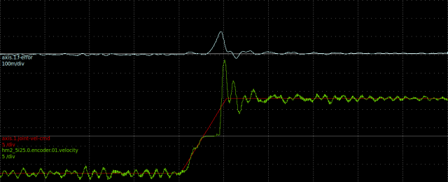
Last edit: 09 Aug 2013 17:03 by Jerre122.
Please Log in or Create an account to join the conversation.
- Jerre122
- Offline
- Junior Member
-
Less
More
- Posts: 33
- Thank you received: 0
11 Aug 2013 22:27 #37566
by Jerre122
Replied by Jerre122 on topic Abene vhf-3 tnc retrofit questions
It turned out the tapered bearings on the Y-axis had some play. Just a little turning of the preload nut solved this.
So now that everything is working properly I would like to start designing and building a control panel.
I have a few things in mind that I would like to know if it's possible or not.
The machine as it is now does not have limit switches, there are 3 proximity sensors, but these are only used for the homing sequence, apparently this went well for some 30 years. Do you think it would be safe to continue trusting the soft limits? If the scales are malfunctioning, wouldn't the f-error become too large almost at once when moving?
Even if I add real end switches I would like to disable jogging before homing anyway. I found a possible solution for doing that in this thread: www.linuxcnc.org/index.php/english/forum...-axis-shell?start=10
However, for some reason jogging remains disabled even after homing.
I would like both a jog speed potmeter and a feed override potmeter on my control panel, is this possible?
Please Log in or Create an account to join the conversation.
- Jerre122
- Offline
- Junior Member
-
Less
More
- Posts: 33
- Thank you received: 0
20 Aug 2014 00:27 - 20 Aug 2014 00:53 #50070
by Jerre122
Replied by Jerre122 on topic Abene vhf-3 tnc retrofit questions
The machine has been finished for some time now. I made a control panel for it, I also changed the jog controls so if you press the cycle start button when jogging it keeps going until you press stop (a program can't be started when the machine is in manual jog mode now). The control panel is loosely based on old deckel dialog panels. Some features are based on heidenhain controllers as well, for example if you press the F button you can type the feed rate you want for jogging en simply press enter.
Here are some videos of the machine:
The test piece I made in the first video was measured on a Mitutoyo CMM, all errors (including roundness) were within 22 micrometers (on a piece 150x150mm) so I'm very happy with it.
The next step is a fourth axis. Does anyone know a good source for DC brushed servo's and drivers that work with +-10V input? All I can find online are brushless or AC servo's and step/dir drivers.
Last edit: 20 Aug 2014 00:53 by Jerre122.
Please Log in or Create an account to join the conversation.
- andypugh
-
- Offline
- Moderator
-
Less
More
- Posts: 23395
- Thank you received: 4971
20 Aug 2014 00:40 #50073
by andypugh
Do you have any particular reason to prefer brushed to brushless? If you are buying the motor and drive as a pair then the commutation method shouldn't really matter.
www.zappautomation.co.uk/electrical-prod...ed-servo-motors.html have some, but I think I would personally prefer
www.zappautomation.co.uk/electrical-prod...075-0039-aa-000.html and a matched AC motor.
However, if I was looking for a servo ad driver I would probably go to eBay. A quick look shows:
www.ebay.co.uk/itm/Dmm-tech-750w-ac-serv...&hash=item4d2267c268
Replied by andypugh on topic Abene vhf-3 tnc retrofit questions
Does anyone know a good source for DC brushed servo's and drivers that work with +-10V input? All I can find online are brushless or AC servo's and step/dir drivers.
Do you have any particular reason to prefer brushed to brushless? If you are buying the motor and drive as a pair then the commutation method shouldn't really matter.
www.zappautomation.co.uk/electrical-prod...ed-servo-motors.html have some, but I think I would personally prefer
www.zappautomation.co.uk/electrical-prod...075-0039-aa-000.html and a matched AC motor.
However, if I was looking for a servo ad driver I would probably go to eBay. A quick look shows:
www.ebay.co.uk/itm/Dmm-tech-750w-ac-serv...&hash=item4d2267c268
Please Log in or Create an account to join the conversation.
- Jerre122
- Offline
- Junior Member
-
Less
More
- Posts: 33
- Thank you received: 0
20 Aug 2014 01:13 #50075
by Jerre122
Replied by Jerre122 on topic Abene vhf-3 tnc retrofit questions
The main reason I want a DC brushed motor is price. I don't need a expensive driver or motor for a fourth axis. A really simple/cheap driver/motor combination would be fine.
I would probably use a stepper if could. However since I already have a Mesa 7i77 I would like to use this card for the fourth axis as well.
I don't want to spend too much money on the servo and driver. I was hoping I could keep the entire cost of the fourth axis under 400EUR.
I would probably use a stepper if could. However since I already have a Mesa 7i77 I would like to use this card for the fourth axis as well.
I don't want to spend too much money on the servo and driver. I was hoping I could keep the entire cost of the fourth axis under 400EUR.
Please Log in or Create an account to join the conversation.
Time to create page: 0.142 seconds