12V encoder interfacing with 7i77, schematic?
- djs14
- Offline
- Senior Member
-

Less
More
- Posts: 56
- Thank you received: 0
24 Feb 2016 18:23 #70579
by djs14
12V encoder interfacing with 7i77, schematic? was created by djs14
Hello all,
I feel like I'm making progress on my project, thanks to you guys!
I'm ready to wire up encoders and make things move, but realized my encoders are 12v out not 5v.
Can I just use a resistor inline to knock down the voltage? These are the axis encoders:
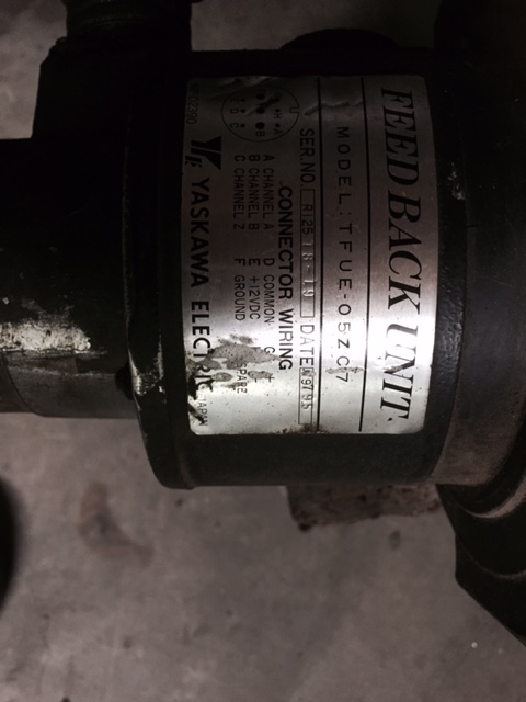
Now on the spindle encoder AND drive, I have no info or wiring diagram. Here's a pic of the encoder.
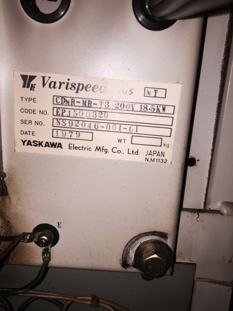
And here's a pic of the drive. I found some info on line for similar part numbers but the numbering scheme did not make sense with what I see on this drive. This is an old Miyano 7BC lathe I'm retro fitting.
Thanks for any input and guidance.
I feel like I'm making progress on my project, thanks to you guys!
I'm ready to wire up encoders and make things move, but realized my encoders are 12v out not 5v.
Can I just use a resistor inline to knock down the voltage? These are the axis encoders:
Now on the spindle encoder AND drive, I have no info or wiring diagram. Here's a pic of the encoder.
And here's a pic of the drive. I found some info on line for similar part numbers but the numbering scheme did not make sense with what I see on this drive. This is an old Miyano 7BC lathe I'm retro fitting.
Thanks for any input and guidance.
Please Log in or Create an account to join the conversation.
- djs14
- Offline
- Senior Member
-
Less
More
- Posts: 56
- Thank you received: 0
24 Feb 2016 22:15 #70585
by djs14
Replied by djs14 on topic 12V encoder interfacing with 7i77, schematic?
Hooking up a couple 100 ohm resistors in series and doing some basic ohms law calc's I came up with a resistance of 1000 ohm for the encoder (ex. A+) leg. With 12V at the encoder, I measured 2v at the first resistor and 1v at the second resistor.
Doing some series ohm's law calculations I could use one 700 ohm resistor to get 5v or use two 1000 ohm resistors (roughly) in series and tap in between the 1000 ohm resistors. (12v/3 = 4vdc) ... maybe too low, but am I understanding the concept correctly? Is one configuration better than the other?
Thank you
Please Log in or Create an account to join the conversation.
- Todd Zuercher
-

- Offline
- Platinum Member
-

Less
More
- Posts: 4757
- Thank you received: 1459
24 Feb 2016 22:24 #70586
by Todd Zuercher
Replied by Todd Zuercher on topic 12V encoder interfacing with 7i77, schematic?
What I think you need to do is build a voltage divider with a couple of resisters.
en.wikipedia.org/wiki/Voltage_divider
en.wikipedia.org/wiki/Voltage_divider
Please Log in or Create an account to join the conversation.
- djs14
- Offline
- Senior Member
-
Less
More
- Posts: 56
- Thank you received: 0
24 Feb 2016 22:34 - 24 Feb 2016 22:38 #70587
by djs14
Replied by djs14 on topic 12V encoder interfacing with 7i77, schematic?
OK thanks. It just seemed too simple to make these encoders work with the mesa hardware ") . Edit: This is true with regards to the X and Z encoders ... the spindle encoder I have no clue on right now nor do I the drive
. Edit: This is true with regards to the X and Z encoders ... the spindle encoder I have no clue on right now nor do I the drive  .
.
cheers
There were schematics clearly labeled righ on the X and Z encoders but nothing on the spindle encoder... just p/n
. Edit: This is true with regards to the X and Z encoders ... the spindle encoder I have no clue on right now nor do I the drive .cheers
There were schematics clearly labeled righ on the X and Z encoders but nothing on the spindle encoder... just p/n
Last edit: 24 Feb 2016 22:38 by djs14.
Please Log in or Create an account to join the conversation.
- cncbasher
- Offline
- Moderator
-

Less
More
- Posts: 1021
- Thank you received: 202
25 Feb 2016 09:41 - 25 Feb 2016 09:42 #70603
by cncbasher
Replied by cncbasher on topic 12V encoder interfacing with 7i77, schematic?
sometimes it's worth just trying the encoders on 5v , iv'e found in 70% of cases they work without any problems
what details do you have on your spindle encoder ? picture etc
what details do you have on your spindle encoder ? picture etc
Last edit: 25 Feb 2016 09:42 by cncbasher.
Please Log in or Create an account to join the conversation.
- djs14
- Offline
- Senior Member
-
Less
More
- Posts: 56
- Thank you received: 0
25 Feb 2016 15:10 - 25 Feb 2016 15:11 #70621
by djs14
Ok thanks for the tip. Right now I've been able to get a lot of things working without re-wire. There's a separate isolated power supply that runs the encoders and some other things. I think it will be easier to just do a voltage divider for now if there's now downside. There's also a tach built into the encoders ... they probably need the 12v .... or am I just being lazy") .
.
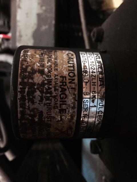
I posted a pic of the spindle encoder above.
There's also a pic of the drive model number above. I found schematics for MT 500 drives but couldn't correlate it to this beast.
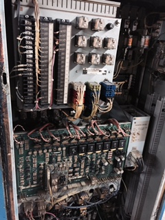
Here's a zoomed back pick of the drive. It's a mammoth. I've seen these drives for sale on ebay and the area on the top left looks to be a little different between models. It is referred to as the "sequence unit". I'm not sure if it's easier to tap into that or figure out how that unit is actually talking to the drive and tap directly into the drive.
Any input here greatly appreciated!
Thank you
Replied by djs14 on topic 12V encoder interfacing with 7i77, schematic?
sometimes it's worth just trying the encoders on 5v , iv'e found in 70% of cases they work without any problems
what details do you have on your spindle encoder ? picture etc
Ok thanks for the tip. Right now I've been able to get a lot of things working without re-wire. There's a separate isolated power supply that runs the encoders and some other things. I think it will be easier to just do a voltage divider for now if there's now downside. There's also a tach built into the encoders ... they probably need the 12v .... or am I just being lazy
.I posted a pic of the spindle encoder above.
There's also a pic of the drive model number above. I found schematics for MT 500 drives but couldn't correlate it to this beast.
Here's a zoomed back pick of the drive. It's a mammoth. I've seen these drives for sale on ebay and the area on the top left looks to be a little different between models. It is referred to as the "sequence unit". I'm not sure if it's easier to tap into that or figure out how that unit is actually talking to the drive and tap directly into the drive.
Any input here greatly appreciated!
Thank you
Last edit: 25 Feb 2016 15:11 by djs14.
Please Log in or Create an account to join the conversation.
- djs14
- Offline
- Senior Member
-
Less
More
- Posts: 56
- Thank you received: 0
27 Feb 2016 02:21 #70701
by djs14
I'm losing counts on the DRO. Tomorrow I will hook up my scope and have a look at the A and B wave forms simultaneously. My resistors are creating a 4.8V wave. Is that potentially my problem? Should I get it right to 5V?
Any other things I should mess with.
The encoders are not differential. I had no wires hooked to the "negative" side of the encoder inputs (a/,b/) on the 7i77. Any chance I should be hooking my encoder pulses to a/ and b/ vs a and b?
It also seemed like hooking up the index pulse garbled the count more. I'll look at that also.
It's pretty cool that I'm getting data to the DRO.... even though it's wrong
cheers
Replied by djs14 on topic 12V encoder interfacing with 7i77, schematic?
What I think you need to do is build a voltage divider with a couple of resisters.
en.wikipedia.org/wiki/Voltage_divider
I'm losing counts on the DRO. Tomorrow I will hook up my scope and have a look at the A and B wave forms simultaneously. My resistors are creating a 4.8V wave. Is that potentially my problem? Should I get it right to 5V?
Any other things I should mess with.
The encoders are not differential. I had no wires hooked to the "negative" side of the encoder inputs (a/,b/) on the 7i77. Any chance I should be hooking my encoder pulses to a/ and b/ vs a and b?
It also seemed like hooking up the index pulse garbled the count more. I'll look at that also.
It's pretty cool that I'm getting data to the DRO.... even though it's wrong
cheers
Please Log in or Create an account to join the conversation.
- djs14
- Offline
- Senior Member
-
Less
More
- Posts: 56
- Thank you received: 0
01 Mar 2016 23:07 - 01 Mar 2016 23:09 #70873
by djs14
Replied by djs14 on topic 12V encoder interfacing with 7i77, schematic?
Got X and Z axes homing to index pulse on encoders and my tool changer working from M6! Huge milestones for me!
Thank you for all the help.
If anyone has any info on my spindle drive and encoder that would be greatly appreciated! Pics of model numbers on first or second post of this thread.
I wanted to backup my files here. Sometimes this computer doesn't see the hard drive ...
cheers all
Thank you for all the help.
If anyone has any info on my spindle drive and encoder that would be greatly appreciated! Pics of model numbers on first or second post of this thread.
I wanted to backup my files here. Sometimes this computer doesn't see the hard drive ...
cheers all
Last edit: 01 Mar 2016 23:09 by djs14.
Please Log in or Create an account to join the conversation.
- PCW
-

- Offline
- Moderator
-
Less
More
- Posts: 17977
- Thank you received: 5275
01 Mar 2016 23:26 #70876
by PCW
Replied by PCW on topic 12V encoder interfacing with 7i77, schematic?
When 7I77 encoders are in TTL mode, they have a TTL threshold (about 1.7V) so I would make sure the input swings as low as possible, less than .5V if possible. This is complicated by the fact that the inputs have 2K ohm pullups to 5V. This means you may need to lower your divider impedance to get good low level
The following user(s) said Thank You: kt600v
Please Log in or Create an account to join the conversation.
- djs14
- Offline
- Senior Member
-
Less
More
- Posts: 56
- Thank you received: 0
17 Mar 2016 17:19 #71821
by djs14
Replied by djs14 on topic 12V encoder interfacing with 7i77, schematic?
file backups
Please Log in or Create an account to join the conversation.
Time to create page: 0.282 seconds