Hydraulic press brake control
- microsprintbuilder
- Offline
- Premium Member
-

Less
More
- Posts: 115
- Thank you received: 4
21 Sep 2018 15:40 - 21 Sep 2018 15:41 #117851
by microsprintbuilder
Hydraulic press brake control was created by microsprintbuilder
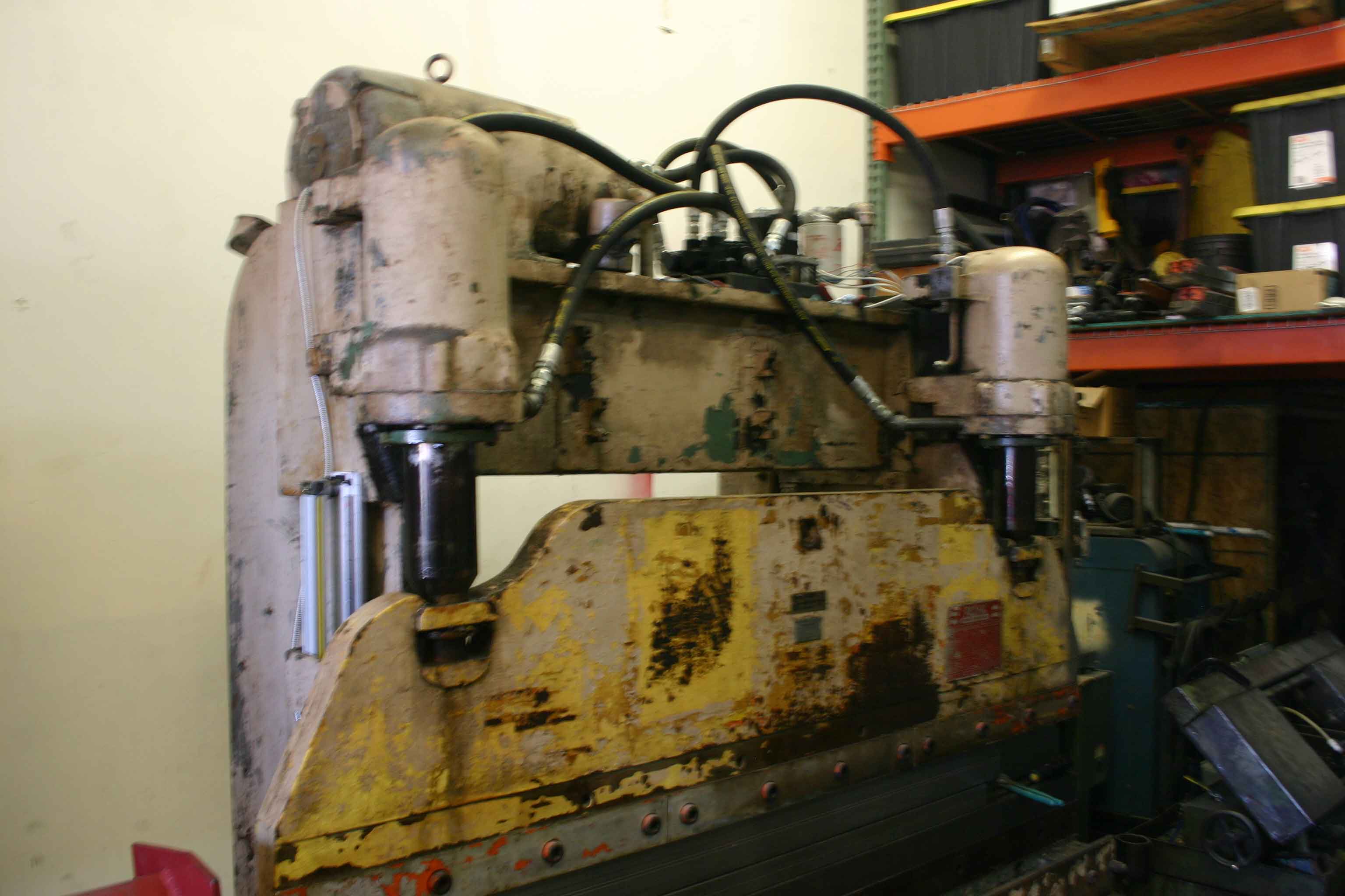
I've purchased a Hydraulic press brake that the valve system was rusted and non repairable. My answer is to use glass scales on each cylinder for synchronization and height control. Originally I tried to use a arduino but it cannot count the encoder / glass scales and do other math at the same time fast enough. My budget doesn't allow for expensive servo valves so I made my own stepper driven two spool valve. I'm looking to use linuxcnc and mesa to make it work. I've built 3 machines so far using linuxcnc and mesa and have always thought of a better way to do it after I'm done. So I'm asking for input on what cards and concepts to impalement it using linuxcnc. As of right now I have linear glass scales attached to each side. and stepper motors have encoders as well. So I need to be able to read 4 encoders and drive to stepper motors back and forth to raise lower and sync.
Last edit: 21 Sep 2018 15:41 by microsprintbuilder.
Please Log in or Create an account to join the conversation.
- Grotius
-

- Offline
- Platinum Member
-

Less
More
- Posts: 2419
- Thank you received: 2348
21 Sep 2018 19:34 #117855
by Grotius
Replied by Grotius on topic Hydraulic press brake control
Hi Steve,
Nice idea !
In the past i have made 3 press brake's my self. The last one was 3000mm 100 ton's with ltp1/parport cnc application running
on Mach3. I have used this press brake for about 1.5 year. It was a quite nice machine and worked with 2 air-hydraulic pump set's
on 800 bar. So i had 2 air valve's to pump the left and right cilinder separate. The height controlling was done by 2 stepper motor's and 2 inductive sensor's. It was a very simple system, but it worked good.
In your case i think when you have connected your lineair glas scale's and stepper motor's and it is configured and working on a Mesa card, it would be handy to make a custom screen layout for your press brake. Also i would make a C component for your press brake
application. When this is done, you can have a application like the Dutch supplier Delem.
www.delem.com/index.php?p=producten
The Delem interface is written in pure C code.
I am interested in your application, so maybe i can help to make a screen design and a c component for the linux society when you have your mesa i/o working.
Please Log in or Create an account to join the conversation.
- microsprintbuilder
- Offline
- Premium Member
-
Less
More
- Posts: 115
- Thank you received: 4
23 Sep 2018 01:16 #117889
by microsprintbuilder
Replied by microsprintbuilder on topic Hydraulic press brake control
sounds good. I'm thinking I'll use a use a 7i92H with 7i85s for the encoders and step control and a 7i75 for the i/0's. It's to bad they don't make a single board to do step gen, encoder and i/o's. They do for analog servo but not step gen. I think I can convert my code I wrote for the arduino into a comp pretty easy. When I get the hardware I'll update here. Thanks for your interest:)
Please Log in or Create an account to join the conversation.
- Grotius
-
- Offline
- Platinum Member
-
Less
More
- Posts: 2419
- Thank you received: 2348
24 Sep 2018 17:26 - 24 Sep 2018 19:34 #117927
by Grotius
Replied by Grotius on topic Hydraulic press brake control
Hi Steve,
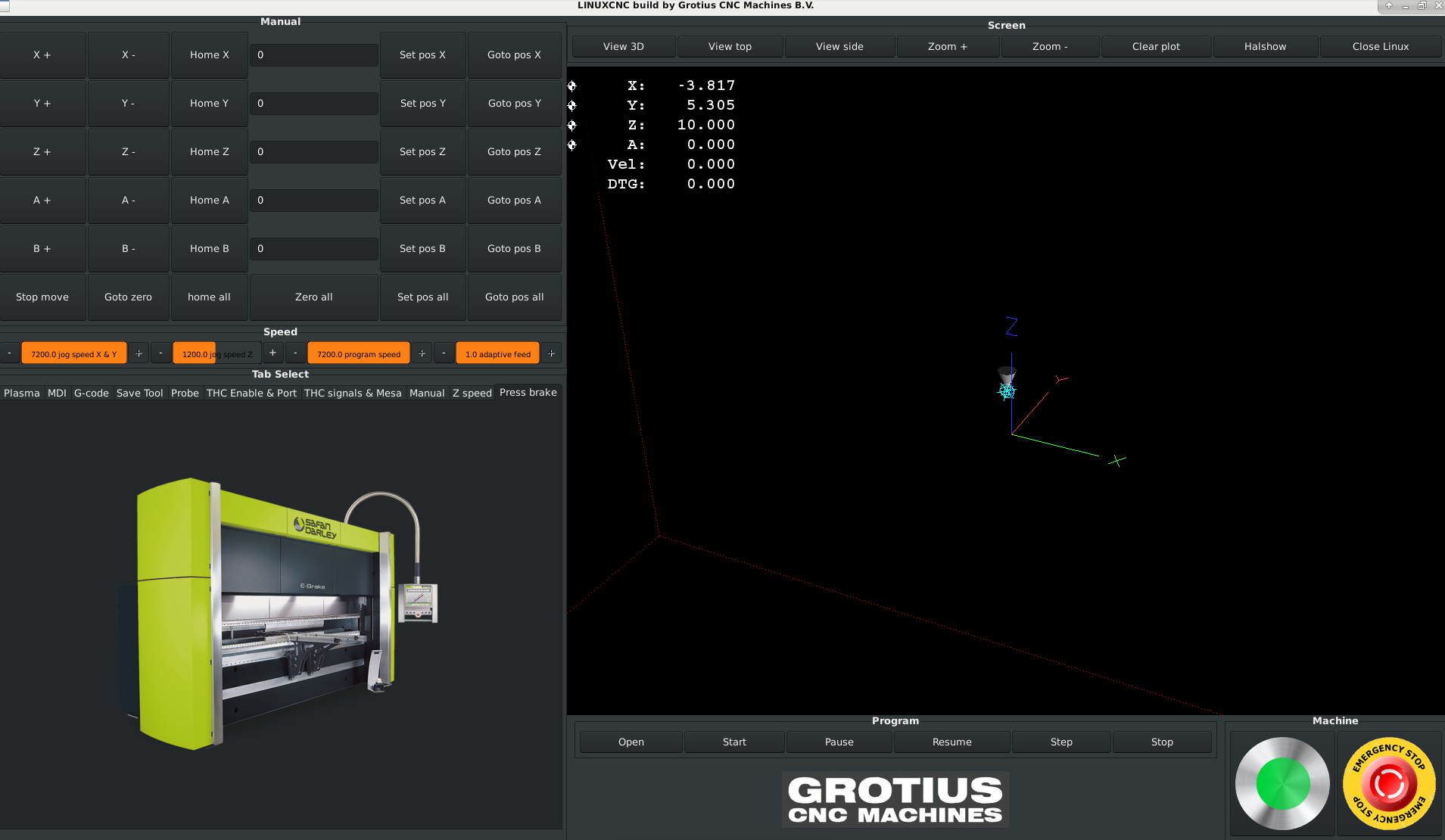
See what we can do. We can make a gui for press brake control, with pictures of the state of the press brake.
Every state need's a picture. So it's just a little photoshopping and a good front picture.
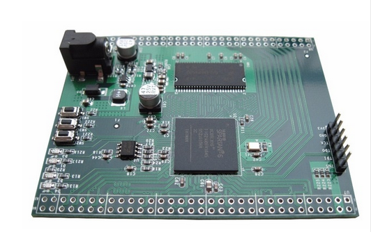
Steve, you can look at the fpga board's of Mesa. Some board's can be almost adjusted unlimited. It need's some experience.
An other way is to make your own fpga interface. I am looking for that.
If you can make the ethernet connection's and the flash it for linuxcnc.... You are almost done for 19 dollars.
I mailed the seller if it's possible to make the ethernet connection for linux. Maybe they can help a little bit to start this board up.
Steve,
See what we can do. We can make a gui for press brake control, with pictures of the state of the press brake.
Every state need's a picture. So it's just a little photoshopping and a good front picture.
Steve, you can look at the fpga board's of Mesa. Some board's can be almost adjusted unlimited. It need's some experience.
An other way is to make your own fpga interface. I am looking for that.
If you can make the ethernet connection's and the flash it for linuxcnc.... You are almost done for 19 dollars.
I mailed the seller if it's possible to make the ethernet connection for linux. Maybe they can help a little bit to start this board up.
Steve,
Have you ever used a working machinekit arduino setup for your press brake concept? So yes, give me the source link. I can look for reverse integrating source code back to linuxcnc.I think I can convert my code I wrote for the arduino into a comp pretty easy
Last edit: 24 Sep 2018 19:34 by Grotius.
The following user(s) said Thank You: tivoi, David-Diy
Please Log in or Create an account to join the conversation.
- microsprintbuilder
- Offline
- Premium Member
-
Less
More
- Posts: 115
- Thank you received: 4
25 Sep 2018 20:16 #117971
by microsprintbuilder
Replied by microsprintbuilder on topic Hydraulic press brake control
I have never use machinekit. I talked to Peter today at mesa. He helped me figure out what I needed. I ordered a 7i96 and a 7i75. He also mentioned that mesa has some new boards coming out. the new 7i95 will have step gen and encoder inputs. It's still in prototype stage though. I have a 7i96 in my plasma table so I've some experience with it. I have to figure out how to move the steppers with encoders only aprox 60 degrees each way to control spool valves that run the cylinders to sync, go up and go down.
Please Log in or Create an account to join the conversation.
- Grotius
-
- Offline
- Platinum Member
-
Less
More
- Posts: 2419
- Thank you received: 2348
26 Sep 2018 14:48 - 26 Sep 2018 14:49 #118010
by Grotius
Replied by Grotius on topic Hydraulic press brake control
If you want synchronised 2 valve control with 2 glass encoders, you have to write a component. Its quite easy for me to make a setup component. Can you give me all your wishes? Input and output signal list. And how you want to control your pressbrake at the user gui?
It would be handy if pcw calls me or mail later this week. Then he can advise wich fpga board i can order. I need something for 6 axis stepper with i/o. I prefer to start wich difficult fpga board that is suitable and has one working hal example.
Mail : michelwijnja
Add : @
Add : gmail.com
It would be handy if pcw calls me or mail later this week. Then he can advise wich fpga board i can order. I need something for 6 axis stepper with i/o. I prefer to start wich difficult fpga board that is suitable and has one working hal example.
Mail : michelwijnja
Add : @
Add : gmail.com
Last edit: 26 Sep 2018 14:49 by Grotius.
Please Log in or Create an account to join the conversation.
- microsprintbuilder
- Offline
- Premium Member
-
Less
More
- Posts: 115
- Thank you received: 4
26 Sep 2018 17:15 #118015
by microsprintbuilder
Replied by microsprintbuilder on topic Hydraulic press brake control
Attached is the sketch I used in the arduino. I'd like to be able to call out a angle and push the down switch and have it move down to bend at that angle. That seems like a lot of math to figure out as you have to adjust for different die's punches and material thickness. So I'd be happy with calling out a depth and then executing it when you push the down foot switch. i think I could just call for a G01 move and have the up switch set to just move up to home. I suppose you could even use G code to have it move down dwell for a second then move back up. The way I have the steppers set up is they only move around 60 degrees each way from center to move the spool valves. In the arduino I wrote the code so when you pushed the down switch it called out a stepper position that made the valve's wide open. then it adjusted that number to each stepper to keep the cylinders moving in sync. once you hit the stop switch it would call out stepper position of zero. i you hit the up switch it would output the opposite numbers. I hadn't got to the gui for the arduino yet. I have purchase a Nextion for that as stage two of the project.
Inputs;
up foot switch
down foot switch
l cylinder home
r cylinder home
l cylinder glass scale
r cylinder glass scale
l stepper encoder 200 ppr
r stepper encoder 200 ppr
e-stop
outputs;
l step / dir
r step /dir
hydrulic pump relay
phase 2
inputs
backstop home
outputs
backstop step / dir
Inputs;
up foot switch
down foot switch
l cylinder home
r cylinder home
l cylinder glass scale
r cylinder glass scale
l stepper encoder 200 ppr
r stepper encoder 200 ppr
e-stop
outputs;
l step / dir
r step /dir
hydrulic pump relay
phase 2
inputs
backstop home
outputs
backstop step / dir
Please Log in or Create an account to join the conversation.
- Grotius
-
- Offline
- Platinum Member
-
Less
More
- Posts: 2419
- Thank you received: 2348
26 Sep 2018 20:30 #118021
by Grotius
Replied by Grotius on topic Hydraulic press brake control
Hi Steve,
Attached a first beginning of in and output's. You can adapt your signal's if you like it.
Do you want to have a home sensor for cilinder left and right on the top, when press brake is in top position?
If your glas scales value's are alway's good. You can use that. I adapted a glas scale height correction, so you don't
have to worry to place them exactly in height. It can be corrected by input value.
I have to add foot up and down.
Do you want to make the closed loop stepper in the component or outside the component in hal?
It's usefull to make the left and right cilinders perfectly synchronizing while the knife is going down.
This can be done in the component. The synchronize input step can be 0.001 to 10mm resolution. That is nice.
Warning: Spoiler!
component pressbrake "Press brake component";
description
"""
Component press brake control, written in C language.
Inspired by Delem Holland.
Todo :
1. --
""";
author "Grotius CNC Machines";
license "GPLv2 or greater";
option singleton yes;
// Startup Pins :
pin in bit Emergency_brake "Emergency brake input";
pin in bit Light_curtain "Connect to safety light curtain";
pin in bit Safety_door_sensor "Connect to safety door sensor";
pin in bit Enable "Enable Press brake component";
pin out bit Enable_true "Control feedback signal for hmi, usable for indicator screen led's";
// Feedback positions :
pin in float Left_glas_encoder_pos_fb "Glas scale encoder position feedback";
pin in float Right_glas_encoder_pos_fb;
pin in float Left_stepper_pos_fb "Stepper motor encoder actual position feedback";
pin in float Right_stepper_pos_fb;
pin in float Backstop_stepper_pos_fb;
pin in float Oil-pressure ;
// Input pins :
pin in bit Left_stepper_home_switch_in "Home switch stepper motor, procedure when linuxcnc start's, process done before activating hydro pump";
pin in bit Right_stepper_home_switch_in;
pin in float Max_speed "Max valve rotation (speed) value";
pin in float Press_speed "Valve rotation (speed) when pressing knife";
pin in float Press_hold_time "Delay time when knife is pressing on product in second's";
//pin in float Backstop_pos "Workpiece backstop input position";
//pin in float Backstop_pos_retract "Backstop retract distance when pressure is increasing";
// Output pins :
pin out float Stepper_motor_pos_cmd_left "Calculated valve output postions";
pin out float Stepper_motor_pos_cmd_right;
pin out bit Hydro_pump_on "Hydraulic pump on/off signal";
pin out bit Machine_light_on "Turn's on the machine light";
pin out float Left_glas_encoder_correction "Calculating encoder_pos_fb + encoder_correction";
pin out float Right_glas_encoder_correcton;
variable double Time; // Delay timer for pressing knife on product
function _;
;;
#include "rtapi_math.h"
typedef enum { INIT, SELECT} state_T;
state_T state = INIT;
FUNCTION(_) {
switch(state){
case INIT:
if(Enable){
state = SELECT;
}
if(!Enable){
state = INIT;
}
break;
case SELECT:
state = INIT;
break;
}
}
The following user(s) said Thank You: David-Diy
Please Log in or Create an account to join the conversation.
- andypugh
-

- Offline
- Moderator
-

Less
More
- Posts: 19875
- Thank you received: 4642
27 Sep 2018 13:11 #118049
by andypugh
Replied by andypugh on topic Hydraulic press brake control
I made a nearly-working GUI for a tube bender a while ago (similar concept)
forum.linuxcnc.org/38-general-linuxcnc-q...ideas?start=10#82686
But starting from scratch (or Gscreen) might be better.
My point with that was that there is no G-code, the files that would be saved would be a plain-text bend list.
forum.linuxcnc.org/38-general-linuxcnc-q...ideas?start=10#82686
But starting from scratch (or Gscreen) might be better.
My point with that was that there is no G-code, the files that would be saved would be a plain-text bend list.
Please Log in or Create an account to join the conversation.
- Grotius
-
- Offline
- Platinum Member
-
Less
More
- Posts: 2419
- Thank you received: 2348
27 Sep 2018 18:43 #118069
by Grotius
Replied by Grotius on topic Hydraulic press brake control
Hi Andy,
Starting from Gscreen is a way to achieve Steve's goal. Mr. Morley, founder of Gscreen has done a great job.
I think G-code is not very useful when using a press-brake. For 3d pipe bending it will be more useful to use G-code because
then the bender can directly work from a cad/cam generated output code.
I read in your provided link that loading and saving data in the gui was a little problem at that time. The press brake application can load and read excel based files and also load and read text file's. The data can be directly adapted into a loaded g-code program in therm's off variables, or the loaded or saved data can be used to execute a press brake program with an almost unlimited press brake sequence. A press brake input screen will be adapted to the gui. We could even make a press brake calculator.
When using the external offset branche g-code is not necessary anymore to move the different axis or joint's.
The only value that is needed in basic for moving joint 0 - 8 is a offset value, speed value, etc. So this option make's life easyer
to write a component code. I use also the negative adaptive speed option in all my application's. I am very happy with this option.
Please Log in or Create an account to join the conversation.
Time to create page: 0.677 seconds