my DIY 900x900x320 CNC router.
- macsddau@linuxcnc
-
 Topic Author
- Offline
- Premium Member
-

Less
More
- Posts: 148
- Thank you received: 29
02 Oct 2022 06:12 #253219
by macsddau@linuxcnc
my DIY 900x900x320 CNC router. was created by macsddau@linuxcnc
This topic replace the one I have created several years ago :
forum.linuxcnc.org/show-your-stuff/37361...teur?start=10#248169
The design of the router is still in work. The first guess of working area was 800x800x300. Now, with more detail design I can rise the dimensions to 900x900x320.
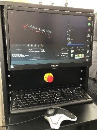
The first difficulties was to ge the PC working for step generating with out latency warnings. The ASRock J3355B-mITX is not a good choice for that. I have recently added a MESA 6i25 FPGA board.
No need to get a good base thread, all steps are gerated by the 6i25.
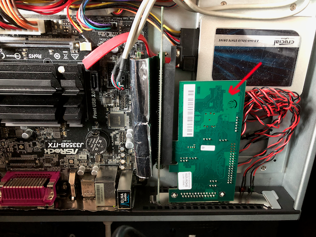
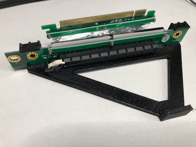
In the 1U 19in box, the MESA board is not connected directly to the mother board. I use a PCIe 16x riser. But the connection with the 6i25 was not secure.
Just created a frame attached to the riser to secure the connection.
Next step : complete the router design.
forum.linuxcnc.org/show-your-stuff/37361...teur?start=10#248169
The design of the router is still in work. The first guess of working area was 800x800x300. Now, with more detail design I can rise the dimensions to 900x900x320.
The first difficulties was to ge the PC working for step generating with out latency warnings. The ASRock J3355B-mITX is not a good choice for that. I have recently added a MESA 6i25 FPGA board.
No need to get a good base thread, all steps are gerated by the 6i25.
In the 1U 19in box, the MESA board is not connected directly to the mother board. I use a PCIe 16x riser. But the connection with the 6i25 was not secure.
Just created a frame attached to the riser to secure the connection.
Next step : complete the router design.
Attachments:
The following user(s) said Thank You: tommylight
Please Log in or Create an account to join the conversation.
- macsddau@linuxcnc
-
Topic Author
- Offline
- Premium Member
-
Less
More
- Posts: 148
- Thank you received: 29
06 Oct 2022 16:40 #253625
by macsddau@linuxcnc
Replied by macsddau@linuxcnc on topic my DIY 900x900x320 CNC router.
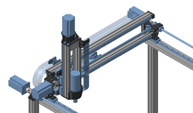
Preparing first part for manufacturing.
This part is form Z axis assembly (in red in the picture) :
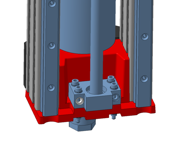
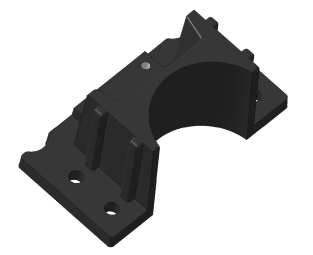
This part will be made in composite with chopped tow carbon fiber and epoxy resine.
The part will be first printed before making a epoxy tool for compressin casting :
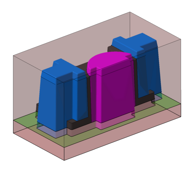
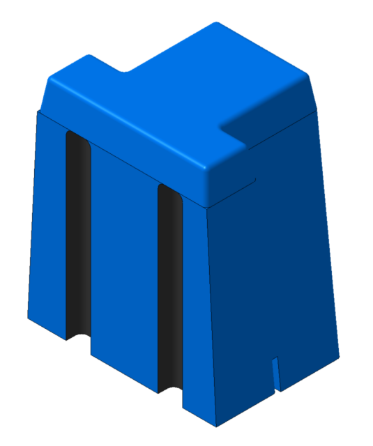
The mouls is 5 parts; 2 mains :
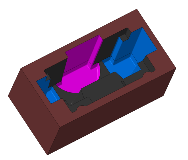
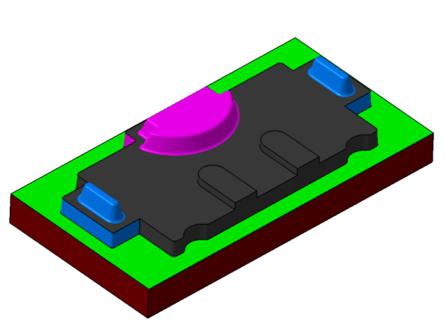
and 3 inserts :

2x
This part is form Z axis assembly (in red in the picture) :
This part will be made in composite with chopped tow carbon fiber and epoxy resine.
The part will be first printed before making a epoxy tool for compressin casting :
The mouls is 5 parts; 2 mains :
and 3 inserts :
2x
Attachments:
The following user(s) said Thank You: tommylight
Please Log in or Create an account to join the conversation.
- macsddau@linuxcnc
-
Topic Author
- Offline
- Premium Member
-
Less
More
- Posts: 148
- Thank you received: 29
14 Dec 2022 22:12 #259508
by macsddau@linuxcnc
Replied by macsddau@linuxcnc on topic my DIY 900x900x320 CNC router.
I'm curently working on router schematic. I have some questions about connecting the BOB to the driver.
I reproduce a simplified view of internal schematic of each board.
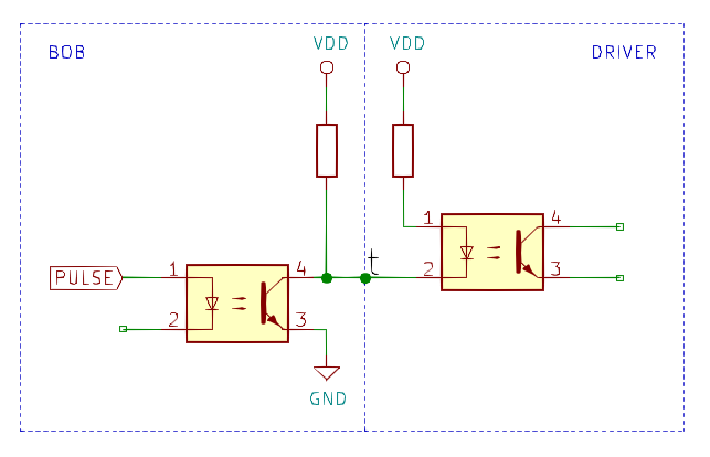
My anderstandig is :
pulse=0 -> t=vdd -> driver output is off (got VDD on 1 & 2 of driver optocoupler => 0 difference voltage)
pulse=1 -> t=gnd -> driver output is on
Is this the good interpretation ?
Is there a risk of damaging the BOB or the driver ?
I reproduce a simplified view of internal schematic of each board.
My anderstandig is :
pulse=0 -> t=vdd -> driver output is off (got VDD on 1 & 2 of driver optocoupler => 0 difference voltage)
pulse=1 -> t=gnd -> driver output is on
Is this the good interpretation ?
Is there a risk of damaging the BOB or the driver ?
Attachments:
Please Log in or Create an account to join the conversation.
- tommylight
-

- Away
- Moderator
-

Less
More
- Posts: 21708
- Thank you received: 7417
14 Dec 2022 22:24 #259511
by tommylight
Replied by tommylight on topic my DIY 900x900x320 CNC router.
Yes, that is correct.
And no, no damage should occur if the resistors are properly calculated and powered by the right voltage, meaning, powering a 5V rated input with 24V will in most cases damage the optocoupler LED.
Some drives have inputs rated for more than 5V, example LAM Technologies drives are OK from 3.3 up to 32 or 35V. Cheap drives are not, and some will refuse to work with 3.3V if they are rated for 5V, but i have never bumped into those.
The following user(s) said Thank You: macsddau@linuxcnc
Please Log in or Create an account to join the conversation.
- macsddau@linuxcnc
-
Topic Author
- Offline
- Premium Member
-
Less
More
- Posts: 148
- Thank you received: 29
14 Dec 2022 22:37 #259512
by macsddau@linuxcnc
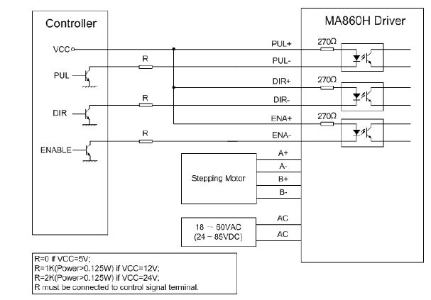
I can't chose R values. They are fixed on each board. Dirver got 270R and the value on the BOB is unknown.
In the driver datasheet recomendations there is no resistor connectected to VDD on the controler side. That's why I'm not sure.
Replied by macsddau@linuxcnc on topic my DIY 900x900x320 CNC router.
VDD come form the same 5V power supply.Yes, that is correct.
And no, no damage should occur if the resistors are properly calculated and powered by the right voltage, meaning, powering a 5V rated input with 24V will in most cases damage the optocoupler LED.
Some drives have inputs rated for more than 5V, example LAM Technologies drives are OK from 3.3 up to 32 or 35V. Cheap drives are not, and some will refuse to work with 3.3V if they are rated for 5V, but i have never bumped into those.
I can't chose R values. They are fixed on each board. Dirver got 270R and the value on the BOB is unknown.
In the driver datasheet recomendations there is no resistor connectected to VDD on the controler side. That's why I'm not sure.
Attachments:
Please Log in or Create an account to join the conversation.
- tommylight
-
- Away
- Moderator
-
Less
More
- Posts: 21708
- Thank you received: 7417
14 Dec 2022 22:56 #259515
by tommylight
Replied by tommylight on topic my DIY 900x900x320 CNC router.
If everything is powered by 5V then no need for the R at all.
The following user(s) said Thank You: macsddau@linuxcnc
Please Log in or Create an account to join the conversation.
- macsddau@linuxcnc
-
Topic Author
- Offline
- Premium Member
-
Less
More
- Posts: 148
- Thank you received: 29
14 Dec 2022 23:09 #259516
by macsddau@linuxcnc
Replied by macsddau@linuxcnc on topic my DIY 900x900x320 CNC router.
In the first schematic, without adding resistor in serial, with pulse=0, is there a risk to have something else than 0V (negative or some positive mV) in driver optocoupler LED that will give the wrong indication to the driver or damage it ?
Please Log in or Create an account to join the conversation.
- tommylight
-
- Away
- Moderator
-
Less
More
- Posts: 21708
- Thank you received: 7417
14 Dec 2022 23:13 #259517
by tommylight
Replied by tommylight on topic my DIY 900x900x320 CNC router.
With 5V you can not damage drive input, even with reverse polarity nothing will happen, of course the drive will not move the motor.
The following user(s) said Thank You: macsddau@linuxcnc
Please Log in or Create an account to join the conversation.
- macsddau@linuxcnc
-
Topic Author
- Offline
- Premium Member
-
Less
More
- Posts: 148
- Thank you received: 29
14 Dec 2022 23:31 #259519
by macsddau@linuxcnc
Replied by macsddau@linuxcnc on topic my DIY 900x900x320 CNC router.
I check with ohm law.
dU=Rb.I+Rd.I+Uled with dU=0 => I=-Uled/(Rb+Rd)
Uled is not a generator => Uled=0 => I=0 => no current !
It was as simple

dU=Rb.I+Rd.I+Uled with dU=0 => I=-Uled/(Rb+Rd)
Uled is not a generator => Uled=0 => I=0 => no current !
It was as simple
The following user(s) said Thank You: tommylight
Please Log in or Create an account to join the conversation.
Time to create page: 0.433 seconds