Reverse Engineering a 5-axis benchtop CNC
- drdoc
- Offline
- New Member
-

Less
More
- Posts: 5
- Thank you received: 3
01 Sep 2023 20:20 - 04 Sep 2023 04:11 #279609
by drdoc
Reverse Engineering a 5-axis benchtop CNC was created by drdoc
Long story, but I'm retrofitting a 7i96 (and probably a ChinaBoB) to a VHF CAM5 S2 dental mill. TL;DR I don't have the license dongle it sold with and don't have the money to pay for the proprietary control software.
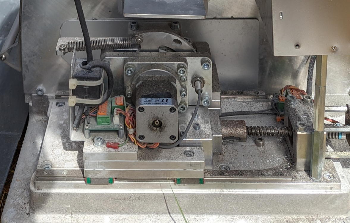
The motion part is pretty straightforward. Open loop NEMA17 steppers with ball screws, I don't expect any problem controlling the motion. I might at some point build a bigger frame but for now, I'm looking at a working envelope of about 4" x 3.5" x 3" plus I think 90 degrees on A and 360 on B.
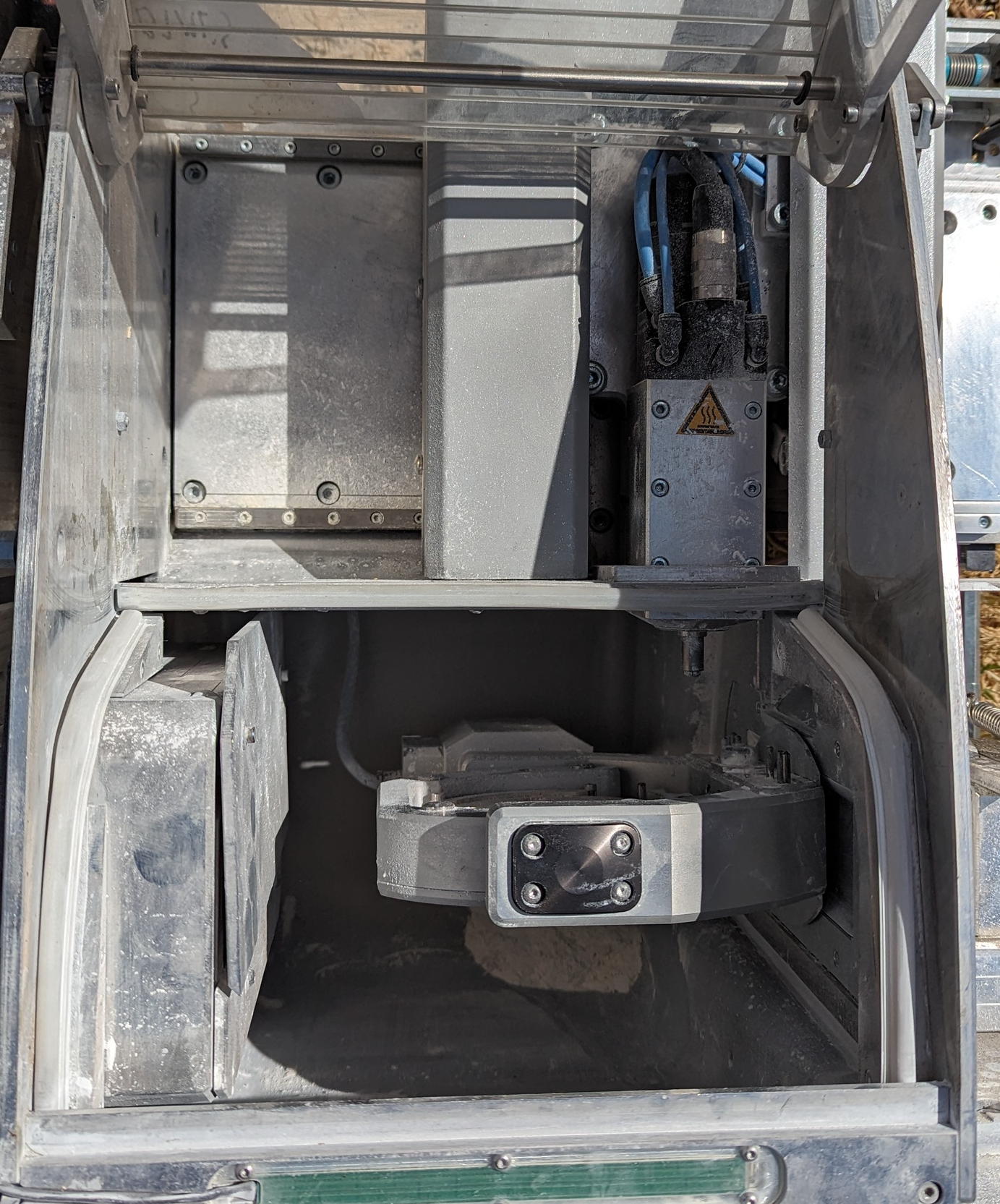

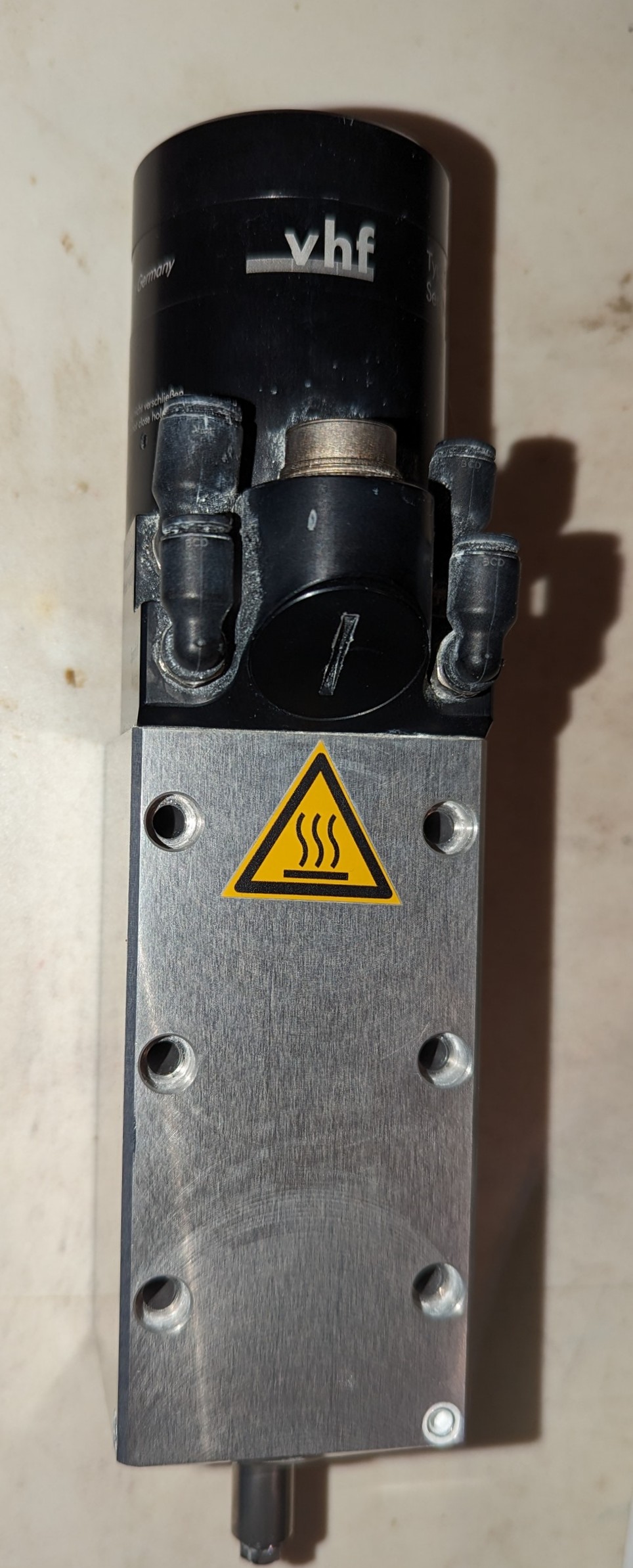
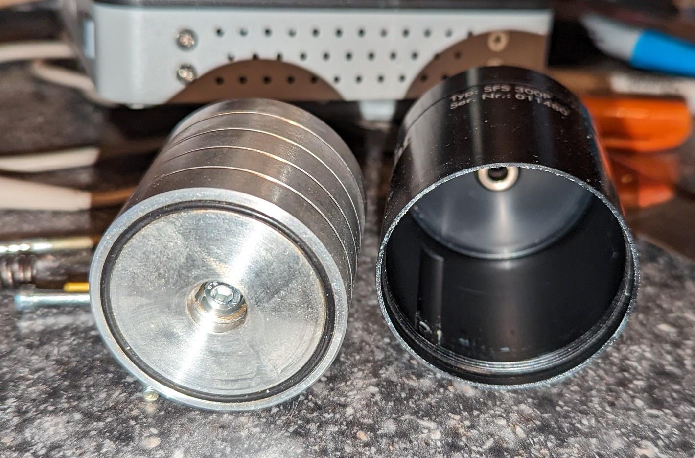
I'm going to either forego the tool changer or re-work it as a 6 or 8 tool instead of 16. Tools with that depth-gauge circlip are way out of my budget, and I think that's integral to operating it as a 16-tool magazine. The spindle, however. It's an VHF-branded SFS 300P. Neither SFS nor VHF publish any pinout, voltage requirement, control frequency range or any useful build info. The motor control daughterboard gives me the pinout for the motor, but I don't have the electronics fu to get any farther than that.
So, my questions are:1) Does anyone here have knowledge or experience with this particular machine? A service manual or any maintenance information would be miraculous.2) Same question for the spindle assembly. I do have the pressure & flow specs for the air seal and chuck controls, but working out the input voltage and speed control are out of my depth.3) Assuming the absence of model-specific details, how should I go about reverse-engineering the motor? I have multimeters and oscilloscope.
Thanks!
Doc
The motion part is pretty straightforward. Open loop NEMA17 steppers with ball screws, I don't expect any problem controlling the motion. I might at some point build a bigger frame but for now, I'm looking at a working envelope of about 4" x 3.5" x 3" plus I think 90 degrees on A and 360 on B.
I'm going to either forego the tool changer or re-work it as a 6 or 8 tool instead of 16. Tools with that depth-gauge circlip are way out of my budget, and I think that's integral to operating it as a 16-tool magazine. The spindle, however. It's an VHF-branded SFS 300P. Neither SFS nor VHF publish any pinout, voltage requirement, control frequency range or any useful build info. The motor control daughterboard gives me the pinout for the motor, but I don't have the electronics fu to get any farther than that.
So, my questions are:1) Does anyone here have knowledge or experience with this particular machine? A service manual or any maintenance information would be miraculous.2) Same question for the spindle assembly. I do have the pressure & flow specs for the air seal and chuck controls, but working out the input voltage and speed control are out of my depth.3) Assuming the absence of model-specific details, how should I go about reverse-engineering the motor? I have multimeters and oscilloscope.
Thanks!
Doc
Attachments:
Last edit: 04 Sep 2023 04:11 by drdoc. Reason: Fixed crazy link text
Please Log in or Create an account to join the conversation.
- tommylight
-

- Away
- Moderator
-

Less
More
- Posts: 21733
- Thank you received: 7425
01 Sep 2023 22:48 #279624
by tommylight
Replied by tommylight on topic Reverse Engineering a 5-axis benchtop CNC
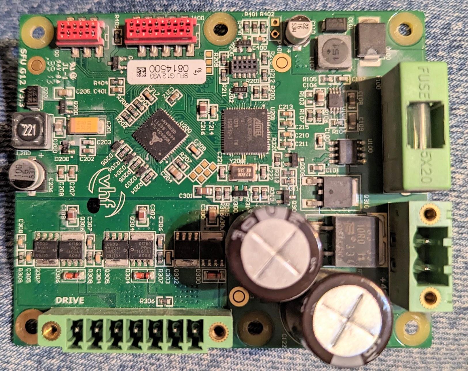
That seems to be the spindle drive, 3 phase, wired in "star" formation.
Take a lot of pictures, upload those here on the forum, a consistent album of wiring would be very useful.
Motor seems a normal 3 phase one, what else goes back to the board from the motor?
Take a lot of pictures, upload those here on the forum, a consistent album of wiring would be very useful.
Motor seems a normal 3 phase one, what else goes back to the board from the motor?
Please Log in or Create an account to join the conversation.
- andypugh
-

- Offline
- Moderator
-
Less
More
- Posts: 19875
- Thank you received: 4642
01 Sep 2023 22:49 #279625
by andypugh
Replied by andypugh on topic Reverse Engineering a 5-axis benchtop CNC
I didn't see a picture of the tools before Imgur started filling the screen with irrelevent and political stuff.
But why would reducing the tool count help? You don't have to use them. And you can probably make your own circlip grooves. Or use the plastic collars (sorry, I am guessing, I got no context from the album link)
But, I am confident that we can work this out between us.
But why would reducing the tool count help? You don't have to use them. And you can probably make your own circlip grooves. Or use the plastic collars (sorry, I am guessing, I got no context from the album link)
But, I am confident that we can work this out between us.
Please Log in or Create an account to join the conversation.
- tommylight
-
- Away
- Moderator
-
Less
More
- Posts: 21733
- Thank you received: 7425
01 Sep 2023 23:03 #279627
by tommylight
Replied by tommylight on topic Reverse Engineering a 5-axis benchtop CNC
I had no irrelevant and political stuff ") , but i hate using those web sites as they have all kinds of trackers, info stealers, malware and spyware, etc etc, hence my insisting on uploading pictures here on the forum.
, but i hate using those web sites as they have all kinds of trackers, info stealers, malware and spyware, etc etc, hence my insisting on uploading pictures here on the forum.
From what i gathered through all the dust, it was a min 5 axis dental machine, has the "plate holder", use materials like titanium, zirconium, and some other stuff that are disk shaped, have NFC or RFID embedded and the machine keeps track of what has already been used, very costly, spindles are usually 50 to 60 KRPM, small tools also expensive, etc.
Fixed several of those, they are also very heavy.
I also have a full PC with PCI controller in it for one of those, probably Italian made, although the machine was bought in 2009 new.
, but i hate using those web sites as they have all kinds of trackers, info stealers, malware and spyware, etc etc, hence my insisting on uploading pictures here on the forum.From what i gathered through all the dust, it was a min 5 axis dental machine, has the "plate holder", use materials like titanium, zirconium, and some other stuff that are disk shaped, have NFC or RFID embedded and the machine keeps track of what has already been used, very costly, spindles are usually 50 to 60 KRPM, small tools also expensive, etc.
Fixed several of those, they are also very heavy.
I also have a full PC with PCI controller in it for one of those, probably Italian made, although the machine was bought in 2009 new.
Please Log in or Create an account to join the conversation.
- drdoc
- Offline
- New Member
-
Less
More
- Posts: 5
- Thank you received: 3
02 Sep 2023 03:45 #279643
by drdoc
Replied by drdoc on topic Reverse Engineering a 5-axis benchtop CNC
@tommylight
You're correct for the most part - this one doesn't use RFID but everything else was spot on. This one uses USB or Ethernet and a program called DentalCNC to send g-code.
The motor is 5k-60krpm, 300w continuous or 600w peak with a 3mm air chuck.
Spindle is plumbed for a mister, has air seals and a "taper purge" as well as the chuck control line.
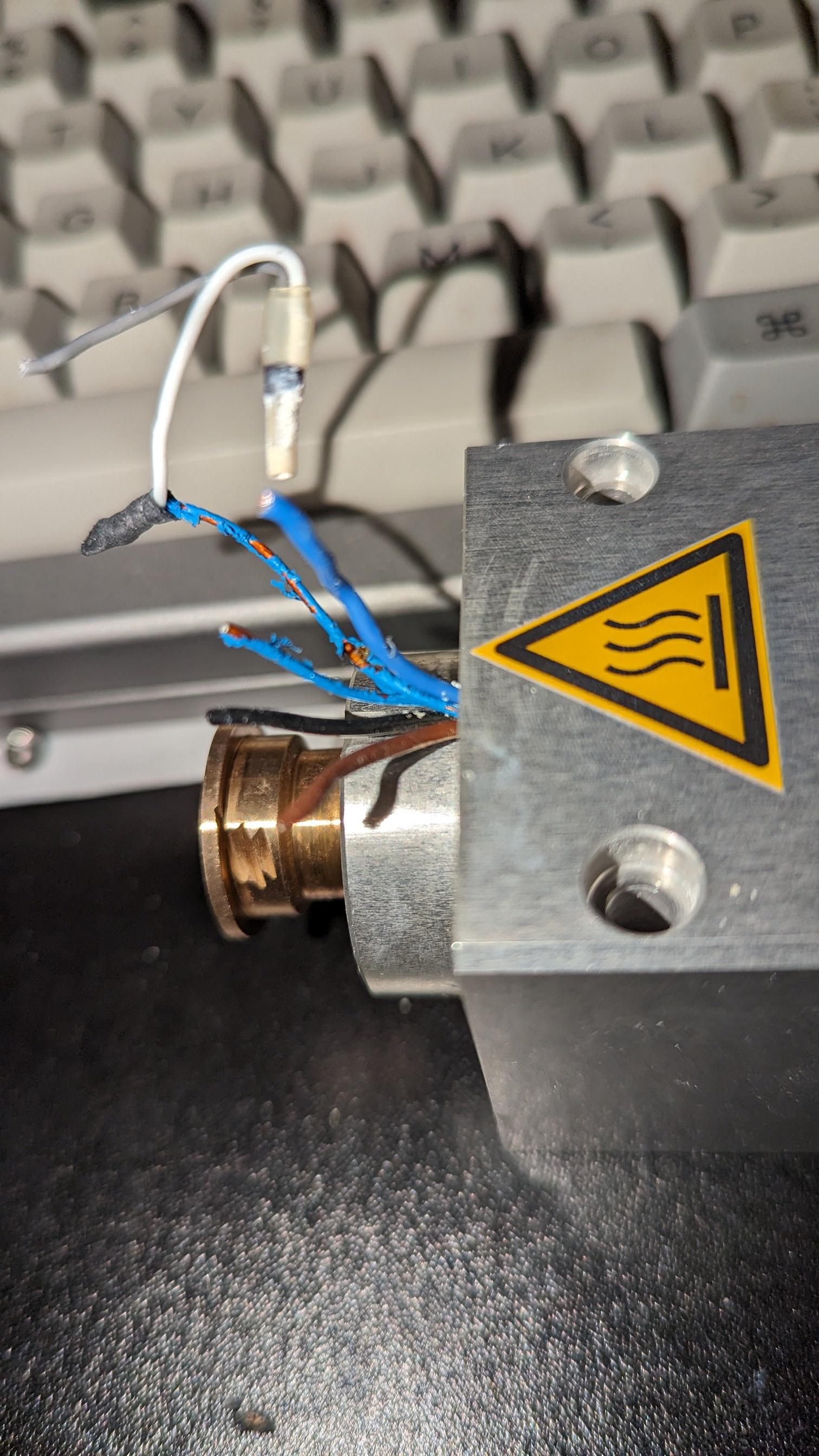
There's a seven wire connection to the motor control board in the photo. I presume that's ground, 3 phase wires and 3 Hall effect sensor wires. I did find a how-to for mapping the phase-sensor relationships & will try that tomorrow.
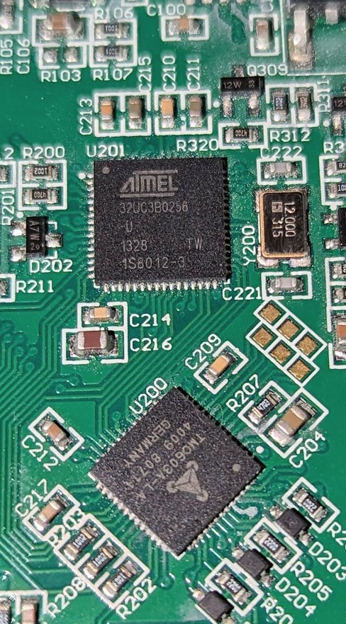
The motor control board has a pretty robust Atmel MCU and a BLDC controller IC, but I suspect that without the factory software I'll be replacing it with a documented BLDC control board
@andypugh
Sorry about the Imgur stuff. I'll migrate the albums to my own server tomorrow.
The purpose of reducing tool count in the magazine is to make room for tools with the more common plastic collar, aka "stuff I can afford".
I appreciate the input! The goal is to make knife parts with this machine - mostly G10, micarta & wood, but hopefully some titanium. If I can learn to talk to this spindle motor the rest is just details.
You're correct for the most part - this one doesn't use RFID but everything else was spot on. This one uses USB or Ethernet and a program called DentalCNC to send g-code.
The motor is 5k-60krpm, 300w continuous or 600w peak with a 3mm air chuck.
Spindle is plumbed for a mister, has air seals and a "taper purge" as well as the chuck control line.
There's a seven wire connection to the motor control board in the photo. I presume that's ground, 3 phase wires and 3 Hall effect sensor wires. I did find a how-to for mapping the phase-sensor relationships & will try that tomorrow.
The motor control board has a pretty robust Atmel MCU and a BLDC controller IC, but I suspect that without the factory software I'll be replacing it with a documented BLDC control board
@andypugh
Sorry about the Imgur stuff. I'll migrate the albums to my own server tomorrow.
The purpose of reducing tool count in the magazine is to make room for tools with the more common plastic collar, aka "stuff I can afford".
I appreciate the input! The goal is to make knife parts with this machine - mostly G10, micarta & wood, but hopefully some titanium. If I can learn to talk to this spindle motor the rest is just details.
The following user(s) said Thank You: tommylight
Please Log in or Create an account to join the conversation.
- drdoc
- Offline
- New Member
-
Less
More
- Posts: 5
- Thank you received: 3
07 Sep 2023 03:08 - 07 Sep 2023 03:10 #280164
by drdoc
Replied by drdoc on topic Reverse Engineering a 5-axis benchtop CNC
Well, I tried to do some further work while tired and distracted, and smoked something in the spindle. I had hoped to avoid tearing it down and was trying to map the phases and sensors, and put 24VDC where it didn't belong.
Oscilloscope shows a nice sinusoidal back emf if I drive the motor externally, and the wiring indicates no Hall effect sensors, so I'm not sure how to drive the thing. Will a simple sensorless (back-emf controlled) BLDC circuit work?
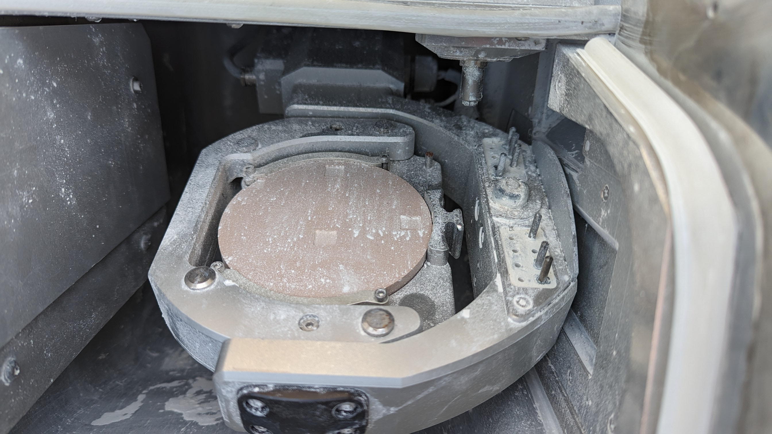
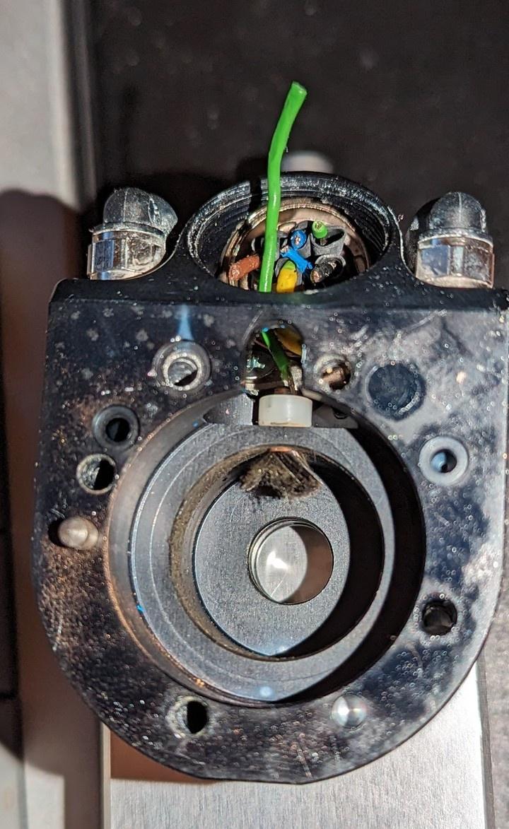
The sensor in the second photo rides on the "dremeled" collar in the first photo
Oscilloscope shows a nice sinusoidal back emf if I drive the motor externally, and the wiring indicates no Hall effect sensors, so I'm not sure how to drive the thing. Will a simple sensorless (back-emf controlled) BLDC circuit work?
The sensor in the second photo rides on the "dremeled" collar in the first photo
Attachments:
Last edit: 07 Sep 2023 03:10 by drdoc.
Please Log in or Create an account to join the conversation.
- gabor
- Offline
- New Member
-
Less
More
- Posts: 1
- Thank you received: 0
14 Jun 2024 09:48 #302994
by gabor
Replied by gabor on topic Reverse Engineering a 5-axis benchtop CNC
good morning i also have such a chuck i wanted to know if you continued to open the chuck and if so how did you do it thank you
Please Log in or Create an account to join the conversation.
- tivoi
-
- Offline
- Senior Member
-

Less
More
- Posts: 68
- Thank you received: 20
15 Jun 2024 01:36 #303026
by tivoi
Replied by tivoi on topic Reverse Engineering a 5-axis benchtop CNC
you need air cylinder for open chuck
release the knife, put knife yous wrench for open chuck,
need put knife into the chuck . There is no knife inside, it can break chuck
release the knife, put knife yous wrench for open chuck,
need put knife into the chuck . There is no knife inside, it can break chuck
Please Log in or Create an account to join the conversation.
Time to create page: 0.413 seconds