Axyz retrofit - spindle wiring 7i96
- rhscdn
- Offline
- Junior Member
-

Less
More
- Posts: 39
- Thank you received: 7
14 Aug 2025 03:07 - 14 Aug 2025 03:13 #333381
by rhscdn
Axyz retrofit - spindle wiring 7i96 was created by rhscdn
I think I have wrapped my head around my stepper motor and limit switch wiring. Regarding the spindle, I have a few questions:
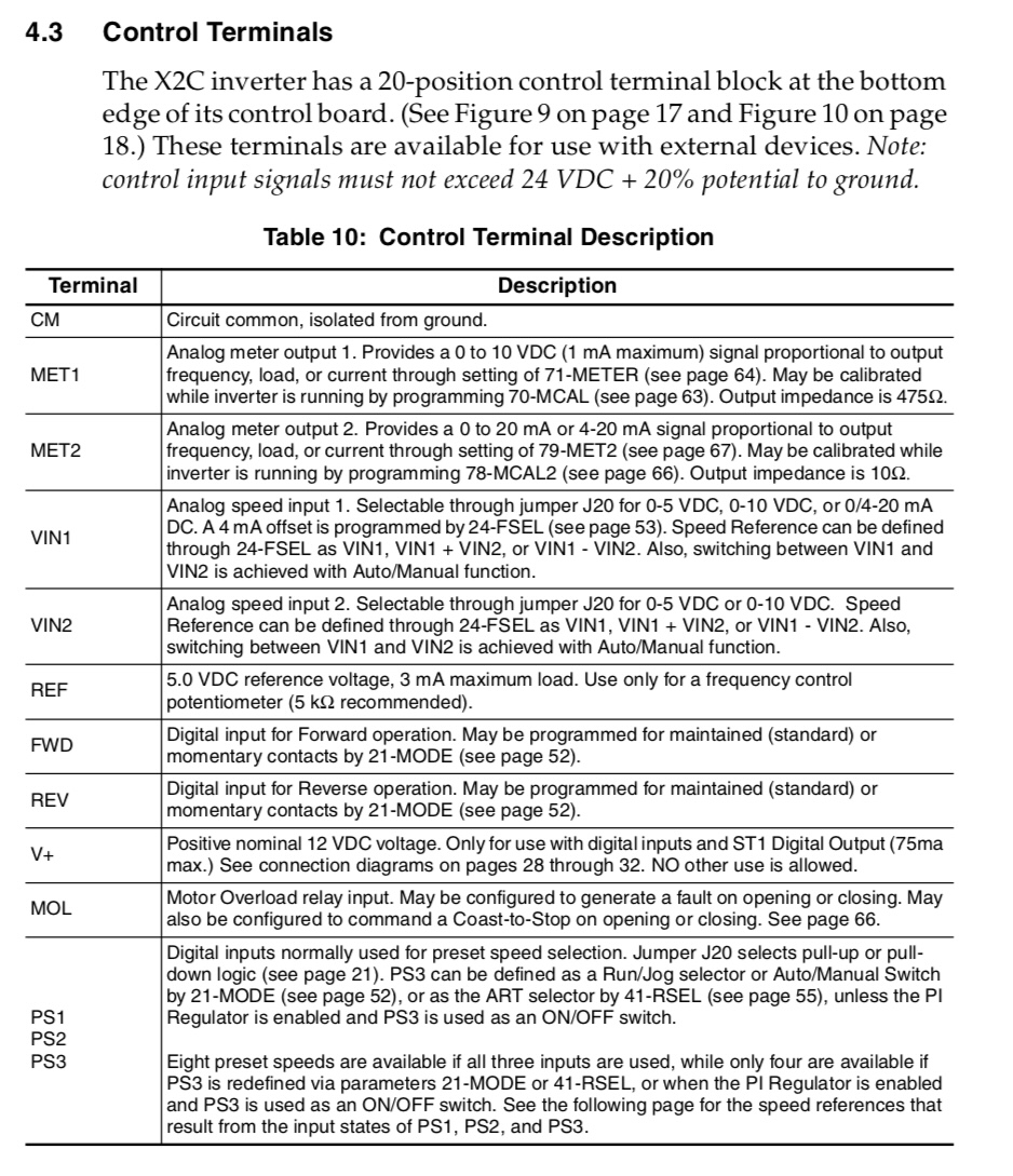
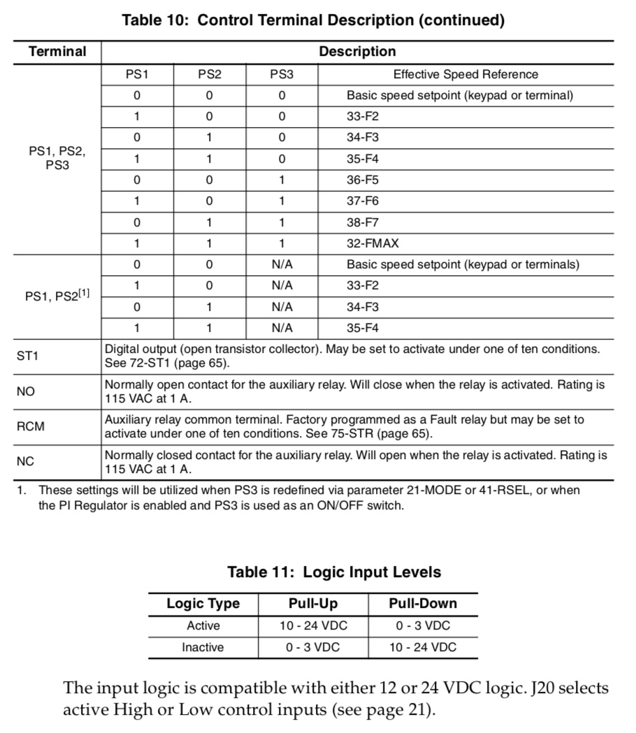
The inverter is a woods eTrac x2c and the manual offers a nearly overwhelming number of options. I was never able to see the spindle working with the stock
AMC controller. I have attached the relevant table from the inverter manual and it seems like I should be able to use the analog spindle interface to provide 0-5vdc signal for speed control (vin). Do I simply use inputs on the 7i96 to conteol fwd/rev and a ground connected to the inverter common? Is that all there is to it?
The original wiring from the AMC controller to the inverter is somewhat different and it isn’t obvious that the AMC was actually able to control the spindle speed. It is connected to use 4 preset spindle speeds and the AMC has wires indicating an acceleration/deceleration signal, as well as some connections to NO and RCM.
Attachments:
Last edit: 14 Aug 2025 03:13 by rhscdn. Reason: URL butchering
Please Log in or Create an account to join the conversation.
- PCW
-

- Away
- Moderator
-

Less
More
- Posts: 17958
- Thank you received: 5263
14 Aug 2025 15:30 - 14 Aug 2025 22:02 #333421
by PCW
Replied by PCW on topic Axyz retrofit - spindle wiring 7i96
Is the a 7I96 or 7I96S?
If 7i96S you should be able to use the 7I96S analog output
connected to the VFDs +5V output, CM, and VIN1
VFD 7I96S
REF SPINDLE+
VIN1 SPINOUT
CM SPINDLE-
Then you would use 2 isolated outputs to drive the VFDs FWD and REV pins, something like:
V+ --> OUT0+
OUT0- --> FWD
V+ --> OUT1+
OUT1- --> REV
If 7i96S you should be able to use the 7I96S analog output
connected to the VFDs +5V output, CM, and VIN1
VFD 7I96S
REF SPINDLE+
VIN1 SPINOUT
CM SPINDLE-
Then you would use 2 isolated outputs to drive the VFDs FWD and REV pins, something like:
V+ --> OUT0+
OUT0- --> FWD
V+ --> OUT1+
OUT1- --> REV
Last edit: 14 Aug 2025 22:02 by PCW.
Please Log in or Create an account to join the conversation.
- rhscdn
- Offline
- Junior Member
-
Less
More
- Posts: 39
- Thank you received: 7
10 Sep 2025 17:01 - 11 Sep 2025 18:13 #334782
by rhscdn
Replied by rhscdn on topic Axyz retrofit - spindle wiring 7i96
I didn't ever say thanks for your reply PCW so a belated thank you! Yes, the 7i96s. The above is working with the VFD set in 'pull-up' logic which is great. I still need to connect the VFD digital outputs (ST1 & STR) to the 7i96 inputs to signal when the motor is running at the commanded speed and when there is a fault. I also initially forgot to configure the PWM signal in pncconf initially.
A few more questions:
1) My VFD programming has the following setup:
A few more questions:
1) My VFD programming has the following setup:
- Minimum frequency of the motor: 100Hz (6000 RPM)
- Maximum frequency of the motor: 300Hz (18000 RPM)
In pncconf I set the max spindle speed to 18000 which I can see in the machine.ini file:[SPINDLE_0] ... MAX_OUTPUT = 18000.0 OUTPUT_SCALE = 36000 OUTPUT_MIN_LIMIT = 0 OUTPUT_MAX_LIMIT = 18000
However, in the same file, I see the qtdragon display section with the following:
[DISPLAY]
DISPLAY = qtvcp qtdragon
...
MAX_SPINDLE_0_OVERRIDE = 1.000000
MIN_SPINDLE_0_OVERRIDE = 0.500000
DEFAULT_SPINDLE_0_SPEED = 500
MIN_SPINDLE_0_SPEED = 100
MAX_SPINDLE_0_SPEED = 2500
...
When I select FWD/REV in the gui, I am seeing the spindle spin in the correct direction and the VFD is correctly driving at 100Hz (i.e. the minimum safe speed for the spindle set in the VFD programming). Do I need to manually change DEFAULT_SPINDLE_0_SPEED, MIN_SPINDLE_0_SPEED, MIN_SPINDLE_0_SPEED? in the QtDragon [DISPLAY] settings in my .ini file or should pncconf be sorting this out?
Last edit: 11 Sep 2025 18:13 by rhscdn.
Please Log in or Create an account to join the conversation.
Time to create page: 0.254 seconds