free CadCam software tryout
- Grotius
-
 Topic Author
- Offline
- Platinum Member
-

- Posts: 2419
- Thank you received: 2348
No additional installation required. It's just a appimage that works from anywhere, like a usb flash drive.
- Currently for testing cam path's output.
- Dxf test file included.
- Can import inkscape + librecad dxf's.
- Outputs gcode
- Todo : keep parts together, etc.
Download :
we.tl/t-aju2T1LtyN
Attachments:
Please Log in or Create an account to join the conversation.
- Reinhard
- Offline
- Platinum Member
-
- Posts: 508
- Thank you received: 94
very nice work and nice to offer an early test
")
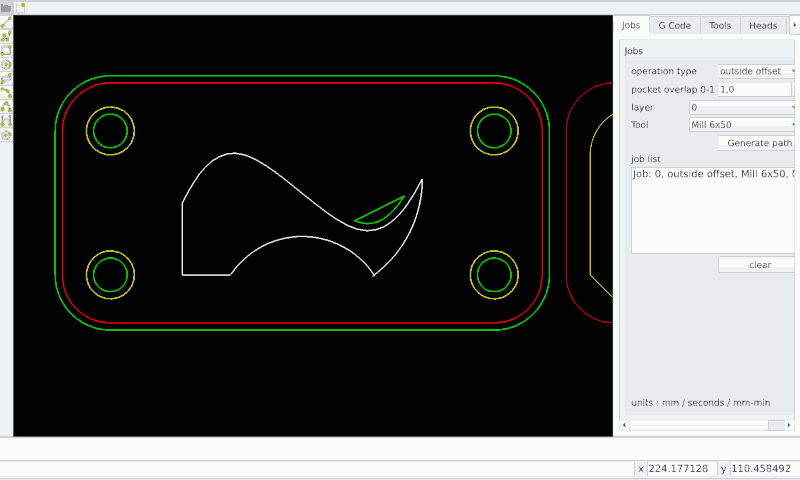
First of all I miss a slider between drawing area and config notebook. I have plenty space on desktop so resizing app is no issue. But notebook stays too small, so that texts are cutted (see next picture).
I just played around with your testfile.
Using operation type "outside offset" leads to this picture:
.
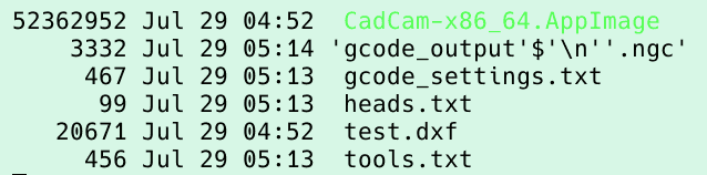
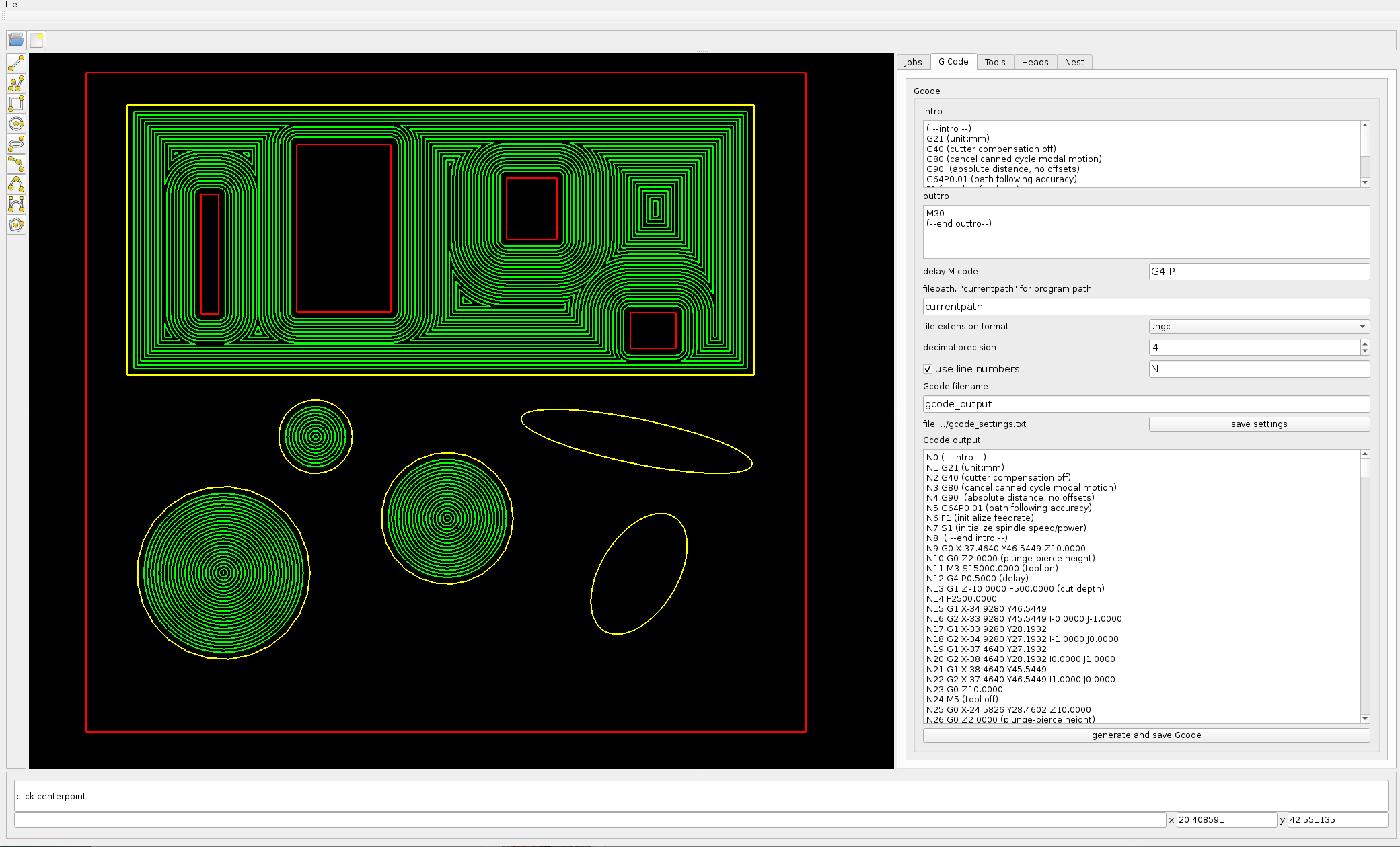
Then I used "generate and save Gcode" which leads to these file entries:
.
Looking at the saved GCode, ...
.
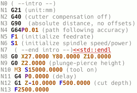
I just realized, that "<<std::endl" is in the intro textbox already, so I could have deleted it before file generation ...
nice option that intro textbox. I think G80 should be part of the default too.
I think, stopping spindle at cut-depth is not a good idea, especially if M5 is the only command in a line. Motion will wait until the spindle is stopped, which could result in ugly artefacts. Better put M5 after "G0 Z10", which starts retiring tool and stops spindle during motion.
Then a lot of space could be saved with unneeded output. Unchanged coordinates don't need to be mentioned in following motion commands and G4 P0 is a big nothing too.
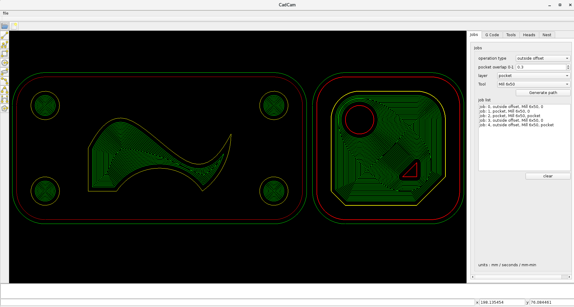
... any way: trying operation type "pocket" on layer "pocket" leads to an endless loop, where I had to kill application.
Your work reminds me of the comparision between cambam and estlcam. Both are windows apps, that are able to run on linux systems. cambam uses mono, estlcam requires a virtualbox.
In optimal environments, both apps generate same/similar result, but the way from drawing to generated code is completely different.
estlcam wants to help the users by doing lot of automatic stuff - with the result, that it fails in non-optimal situations.
cambam just helps the user and does nothing automatically. So here you have more work to achieve gcode generation, but you can successful solve very complicated situations. cambam supports many more filesystems, including stl - which is really handy
When you import a file, you get a bunch of lines/linesegments - and you have to select the lines you want to build the shape to work out.
So I think, it would be better for your app, if you allow the user to select a shape. Then the user could select inside or outside - probably less work for you and better result, as you can't foresee any possible situations.
In cambam you can select two (or more) shapes. If they are concentric, it switches to pocket with isle handling.
If you don't know cambam or estlcam, it would be worth a try.
cheers Reinhard
Attachments:
Please Log in or Create an account to join the conversation.
- tommylight
-

- Away
- Moderator
-

- Posts: 21533
- Thank you received: 7339
Same here.... any way: trying operation type "pocket" on layer "pocket" leads to an endless loop, where I had to kill application.
Please Log in or Create an account to join the conversation.
- Grotius
-
Topic Author
- Offline
- Platinum Member
-
- Posts: 2419
- Thank you received: 2348
1. Tooldelay appears only in the gcode if tooldelay > 0.
2. For milling and drilling the M5 is at safe height. For plasma and oxyfuel the M5 it at cutheight.
3. Added G80 to intro.
4. Added sliders to window.
5. Removed the "std::endl" from the generated intro.
6. Added open contour path's.
7. Repaired gcode filename output, nextline '\n' sign removed, at next release.
Updated CadCam program :
we.tl/t-BQlykj91VN
This update includes :
- Removed unchanged coordinates don't need to be mentioned in following motion.
we.tl/t-XkJMkljBIH
I made a permanent program download on github :
github.com/grotius-cnc/QT_CadCam_rev0/releases/tag/v1.0
@Reinhard,
Thank you for your comments.
So I think, it would be better for your app, if you allow the user to select a shape. Then the user could select inside or outside - probably less work for you and better result, as you can't foresee any possible situations.
This selection model, we do in the near future, and is quite easy to do.
First i need to implement the "keep parts together" as it is more important now.
Strange, for the pocket operation. Try to draw two rectangular shapes in each other and do the pocket operation.
For info : The pocket needs to have a yellow outside color at this moment (ccw direction). Later on, it will be programmed that a red outside color is also possible.
I see i have to integrate the ellipse offset's for a pocket.
Had a look at cambam and estlcam. Both are nice program's. Cost's from 50 up to 100 euro for a licence.
Still cheaper then Sheetcam.
Later on we can do a Stl file input. But at that time i need help
from other programmers that will join the party. Then we can also add a more robust dxf import and export library etc.
The pocket result :
Attachments:
Please Log in or Create an account to join the conversation.
- Reinhard
- Offline
- Platinum Member
-
- Posts: 508
- Thank you received: 94
.
But you can try both programs without license.Had a look at cambam and estlcam. Both are nice program's. Cost's from 50 up to 100 euro for a licence.
I mentioned these cams, as they couldn't be more different.
Estlcam has stylish look and is easy to use. Good for easy jobs, but will fail on real jobs.
Cambam has outdated look and weird input, but great functionality which comes handy with real and complicated jobs. And I love the hierarchic config
.
Try to open the ellipse shape at a corner, so that lines don't touch, or that lines cross each other. I know several designers, that don't care for exactness of drawings.Then we can also add a more robust dxf import
update:
I tried your app from github - looks like github does not contain your changes/updates, so no news.
I had a closer look at the tool definition tab ...
You should distinct between tool properties (like tool diameter) and job properties like travel height, feed rate and all others.
Here's a sample of tool-properties from another cam (which checks collision and the like):
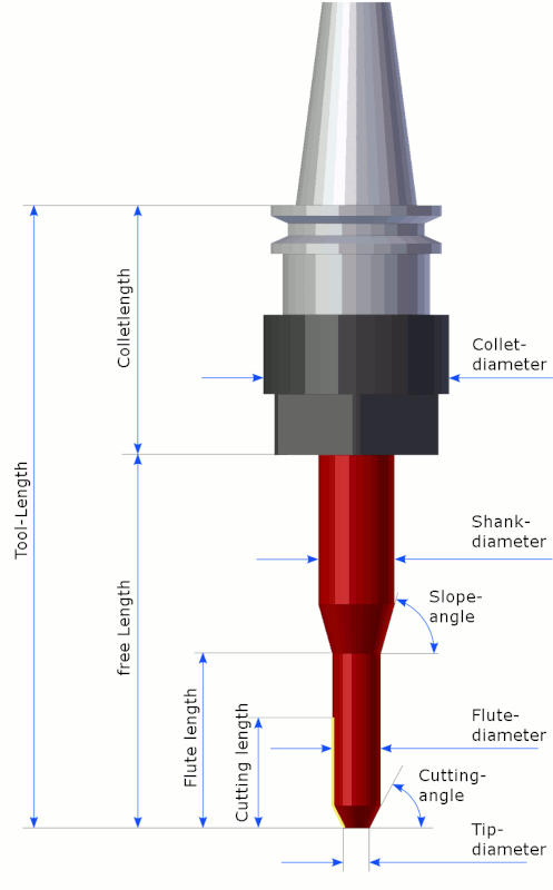
So all properties from your "Tools"-tab below "Name edit" are job-properties (except tool diameter). And Job-properties should be changed for each job ...
... or save presettings for different materials ...
With metal milling top of workpiece is often at -1 (if top is touched by a probe), so the top is expected to be milled all over. But that is very likely a job for a different tool.
So don't do too much at once.
... and if you recall the first picture from my first test:
May be, I want to cut the outline of the workpiece with a different tool then the insides of the holes. Therefore it is evident to limit toolpath generation.
Attachments:
Please Log in or Create an account to join the conversation.
- rodw
-

- Offline
- Platinum Member
-
- Posts: 11878
- Thank you received: 4027
I know several designers, that don't care for exactness of drawings.
Only several? So many designers have no clue of the real world. Those that have hands on in machine shops have a real advantage if the machine shop teaches them how to save hours of work on the shop floor with a few minutes of their time.
Please Log in or Create an account to join the conversation.
- Reinhard
- Offline
- Platinum Member
-
- Posts: 508
- Thank you received: 94
a friend is architect and sometimes he asks me to create a 3D-model from his drawings for presentation purpose. I never got a drawing, that was usable to extend. I always had to start from scratch following the dimensions from drawing only.
Please Log in or Create an account to join the conversation.
- Grotius
-
Topic Author
- Offline
- Platinum Member
-
- Posts: 2419
- Thank you received: 2348
I split my post up in two.
First here is a updated Cadcam program to download :
github.com/grotius-cnc/QT_CadCam_rev0/releases/tag/v1.1
Update includes :
1.Contour selection by mouse, to select specific contours by user. Morpf contours into new layers that can be used for jobs.
2.Repaired file output name by deleting '\n' sign in filename.
3.Tooldelay only appears in gcode when tooldelay>0.
4.Added G80 to gcode intro.
5.Added sliders to window, users now can adjust parts of the screen layout.
6.Added open contour path's to contour class and gcode output.
7.Removed the "std::endl" from the generated intro.
8.For milling and drilling the M5 is at safe height. For plasma and oxyfuel the M5 it at cutheight.
And a version with above updates and autonesting enabled :
github.com/grotius-cnc/QT_CadCam_rev0/releases/tag/cadcam.v1.2
** had to solve a java issue first. Downgraded the java compiler to JDK1.8 to be compatible with opensource java
that lives on standard linux systems. This to avoid that users have to update java first.
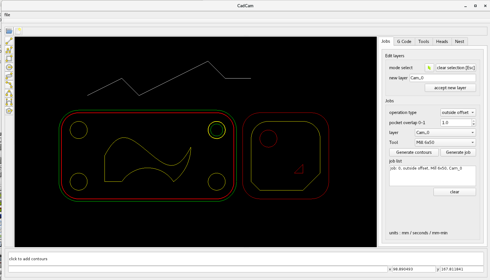
Example of contour selection by mouse, wich result in a layer edit. User has selected one contour + one hole to cut
in this example.
You need to mention that red=cw, yellow is ccw contour.
You have to practice a little bit to understand a yellow outside offset is going
to be a inside offset.
Attachments:
Please Log in or Create an account to join the conversation.
- Grotius
-
Topic Author
- Offline
- Platinum Member
-
- Posts: 2419
- Thank you received: 2348
So all properties from your "Tools"-tab below "Name edit" are job-properties (except tool diameter). And Job-properties should be changed for each job ...
... or save presettings for different materials ...
Will bring back feedrate, cut depth, rpm etc to the job page and keep the current tool page as is.
Passing reference value's from tool page to job page when a tool is selected.
With metal milling top of workpiece is often at -1 (if top is touched by a probe), so the top is expected to be milled all over. But that is very likely a job for a different tool.
So don't do too much at once.
I preferr to hold Z=0 as top of workpiece, to avoid confusion. Mostly of time the plasma users use cutheight z=0.
... and if you recall the first picture from my first test:
May be, I want to cut the outline of the workpiece with a different tool then the insides of the holes. Therefore it is evident to limit toolpath generation.
This is now possible. User can select contours by mouse click and do specific jobs for the selected contours !
Reinhard, I was curious if you are the guy involved by a linuxcnc nml project?
Please Log in or Create an account to join the conversation.
- Reinhard
- Offline
- Platinum Member
-
- Posts: 508
- Thank you received: 94
Well, I work on a mill, where I handcode all my milling jobs at the machine from printed drawings.With metal milling top of workpiece is often at -1 (if top is touched by a probe), so the top is expected to be milled all over. But that is very likely a job for a different tool.
So don't do too much at once.
I preferr to hold Z=0 as top of workpiece, to avoid confusion. Mostly of time the plasma users use cutheight z=0.
Sometimes I have to workout parts from raw steel, which has an unsteady surface.
But I have to admit - I always work in 3D, where dimensions depend on the workpiece origin.
Sometimes I touch the surface of the working table as Z-origin and the workpiece top surface is in positive Z-dimensions.
.
Yes, I wrote a replacement for axis , but I didn't want to code opengl, so I extended jmonkey for 3D previewReinhard, I was curious if you are the guy involved by a linuxcnc nml project?
I added a toolmanager to my app, that is able to support all properties from the tool picture I posted. That toolmanager can than export tooltables for cam and/or linuxcnc.
Please Log in or Create an account to join the conversation.