Workflow for LinuxCNC / PlasmaC tubing notcher
- markbaenen
- Offline
- New Member
-

Less
More
- Posts: 19
- Thank you received: 18
14 Feb 2024 16:33 #293322
by markbaenen
Workflow for LinuxCNC / PlasmaC tubing notcher was created by markbaenen
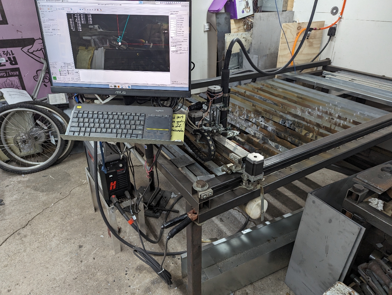
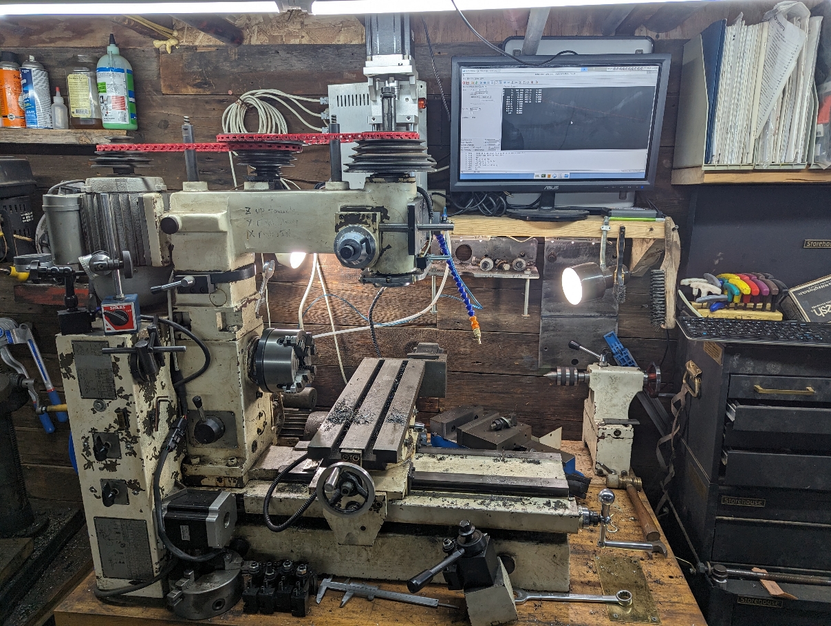
I'm looking for very specific info on workflow for using a PlasmaC tubing notcher (that I really want to build). I've looked up a bunch of topics but can't wrap my head around this.I have a PlasmaC powered plasma table (pic) and I am very familiar with designing parts in FreeCAD -> export as DXF -> import drawing in SheetCAM -> produce G code with PlasmaC post -> load G code into PlasmaC -> Cut. I also have a LinuxCNC powered 3-in-1 with Axis (pic) and for the mill I do very much the same flow except using the Axis post. What I envision is taking a tube frame model from SolidWorks, say a Dune Buggy frame, grab an individual member from the frame (a tube section) -> feed it into SheetCAM (with his plug-in) -> notch tube on rotary axis plasma cutter -> Weld frame together. Anyone have a specific workflow example of how this is done?
Attachments:
Please Log in or Create an account to join the conversation.
- tommylight
-

- Away
- Moderator
-

Less
More
- Posts: 21692
- Thank you received: 7414
14 Feb 2024 18:01 #293326
by tommylight
Replied by tommylight on topic Workflow for LinuxCNC / PlasmaC tubing notcher
Assuming tube is round, everything can be done in two dimensions wrapped around an axis, so no need for complicated 4 axis software.
I use X axis usually as the rotary axis, make separate configs for each tube perimeter and do all the drawings in Inkscape in 2D.
Square tubing is super easy or very complicated, depending on what you want to do. No cuts from side to side = easy as it is just 2D on a single plane.
SheetCAM has something for square tubing and 4 axis, but i never used it.
The following user(s) said Thank You: markbaenen
Please Log in or Create an account to join the conversation.
- markbaenen
- Offline
- New Member
-
Less
More
- Posts: 19
- Thank you received: 18
14 Feb 2024 20:06 #293333
by markbaenen
Replied by markbaenen on topic Workflow for LinuxCNC / PlasmaC tubing notcher
That's a great open-source solution, which I am totally into, but for this project I am wed to Solidworks - mostly because it is so ubiquitous. I know FreeCAD a lot better myself. How does one get the cut path off the tube (yes ROUND) and out of Solidworks?
Mark
Mark
Please Log in or Create an account to join the conversation.
- rodw
-

- Offline
- Platinum Member
-

Less
More
- Posts: 11986
- Thank you received: 4083
14 Feb 2024 21:02 #293342
by rodw
Replied by rodw on topic Workflow for LinuxCNC / PlasmaC tubing notcher
This is super simple in Solidworks or any CAM system that supports sheet metal.
Simply design your tube with all its holes, then add an extruded cut through one side of the tube the full length. Use a minimal width 0.01mm or smaller.
So then convert to sheetmetal and flatten. This gives you a perfect 2D pattern on a single plane that Tommy describes.
For each tube size, create a seperate config with different steps per mm setting based on the circumference of the tube.
Please Log in or Create an account to join the conversation.
- rodw
-
- Offline
- Platinum Member
-
Less
More
- Posts: 11986
- Thank you received: 4083
14 Feb 2024 21:06 #293343
by rodw
Replied by rodw on topic Workflow for LinuxCNC / PlasmaC tubing notcher
Easy, Flatten your part and save a DXF file. I use sheetcam to convert to gcodeHow does one get the cut path off the tube (yes ROUND) and out of Solidworks?
Mark
The following user(s) said Thank You: tommylight, markbaenen
Please Log in or Create an account to join the conversation.
- markbaenen
- Offline
- New Member
-
Less
More
- Posts: 19
- Thank you received: 18
19 Feb 2024 16:55 #293770
by markbaenen
Replied by markbaenen on topic Workflow for LinuxCNC / PlasmaC tubing notcher
Thank you guys for your help! It took a couple days to wrap my head around this, but I've made progress.
I selected a body from an assembly and saved it as a new part. Now the new part - I just have to cut a line down it and flatten with sheetmetal - makes sense. A couple pics for documentation:
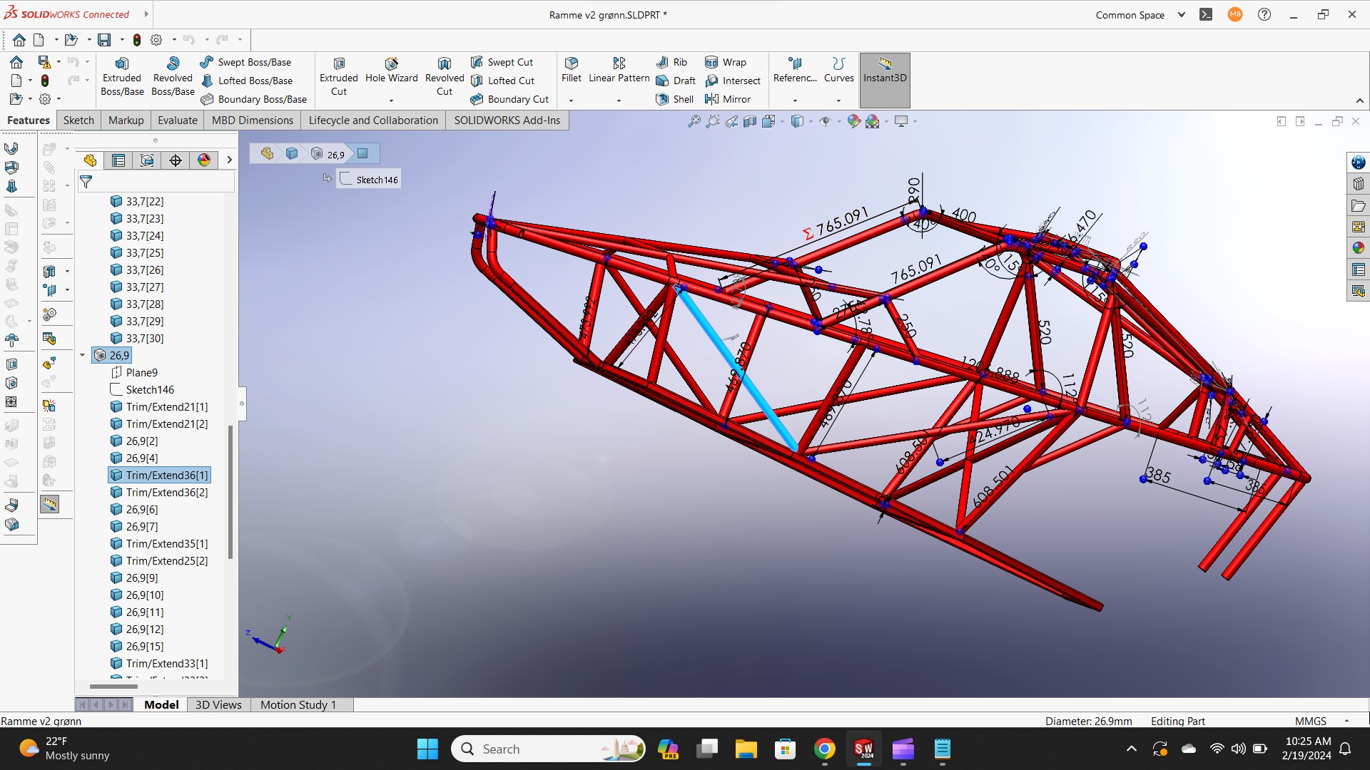
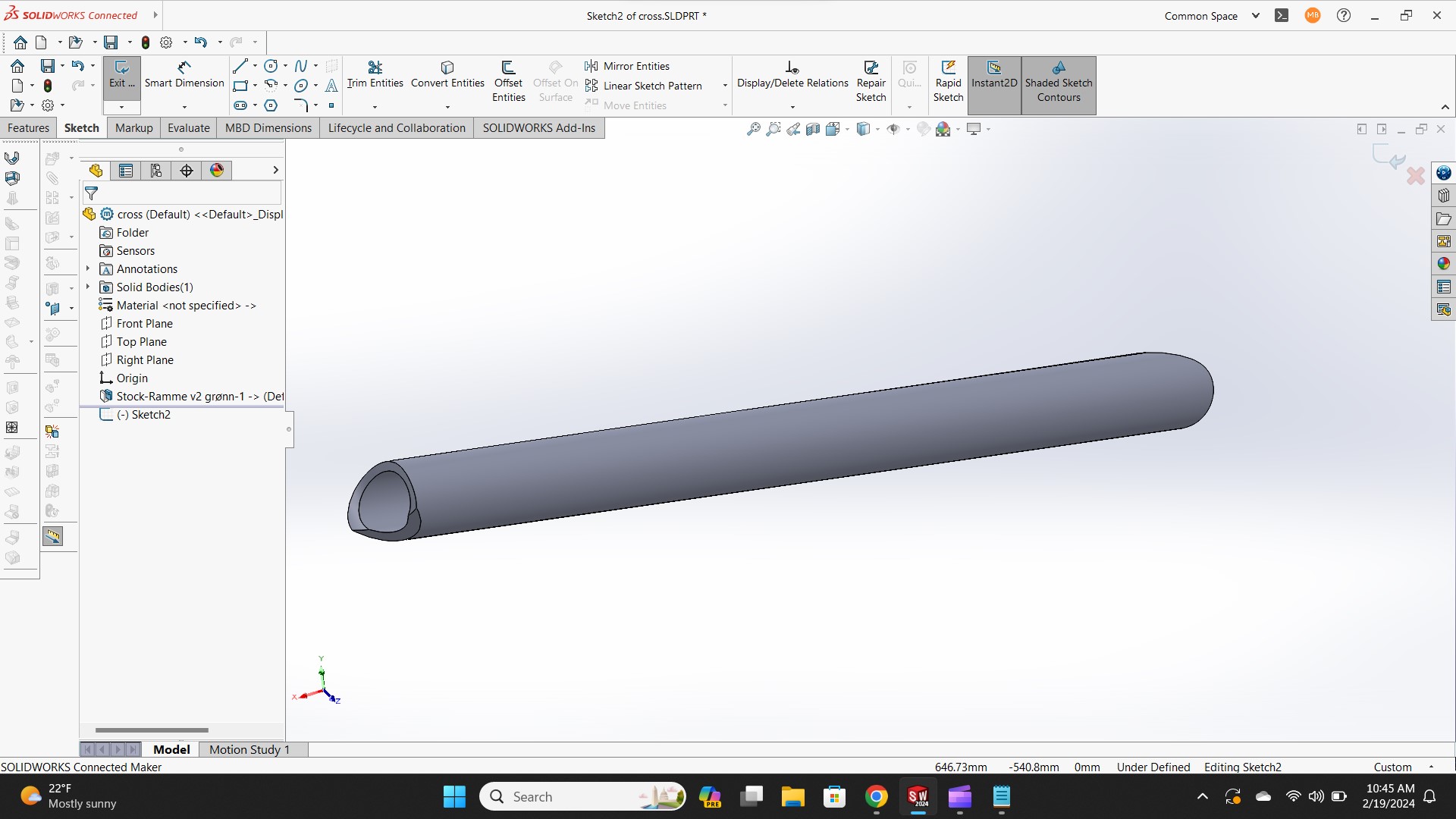
I selected a body from an assembly and saved it as a new part. Now the new part - I just have to cut a line down it and flatten with sheetmetal - makes sense. A couple pics for documentation:
Attachments:
The following user(s) said Thank You: tommylight, rodw
Please Log in or Create an account to join the conversation.
Time to create page: 0.371 seconds