Quote illustration - for HAL
- zz912
-
 Topic Author
- Offline
- Platinum Member
-

Less
More
- Posts: 592
- Thank you received: 96
21 Apr 2020 15:54 - 21 Apr 2020 15:56 #164976
by zz912
Quote illustration - for HAL was created by zz912
Dear Mr. Mrs,
I would like to offer you a picture for the HAL chapter:
linuxcnc.org/docs/2.8/html/hal/intro.html
You might like to use it. Nothing in the picture was overused. I drew a picture in CAD. I can add a potentiometer to represent the parameter.
I would like to offer you a picture for the HAL chapter:
linuxcnc.org/docs/2.8/html/hal/intro.html
You might like to use it. Nothing in the picture was overused. I drew a picture in CAD. I can add a potentiometer to represent the parameter.
Attachments:
Last edit: 21 Apr 2020 15:56 by zz912. Reason: I forgot picture.
The following user(s) said Thank You: tommylight
Please Log in or Create an account to join the conversation.
- bbsr_5a
- Offline
- Platinum Member
-
Less
More
- Posts: 544
- Thank you received: 106
22 Apr 2020 09:12 #165057
by bbsr_5a
Replied by bbsr_5a on topic Quote illustration - for HAL
this drives New people crazy as it suggests hardware Cabeling
HAL is Virtual Software giving the Real PIN a usefull Name
and connecting it to the Virtual Controll Pin inside the CNC controll
HAL is Virtual Software giving the Real PIN a usefull Name
and connecting it to the Virtual Controll Pin inside the CNC controll
Please Log in or Create an account to join the conversation.
- zz912
-
Topic Author
- Offline
- Platinum Member
-
Less
More
- Posts: 592
- Thank you received: 96
22 Apr 2020 10:13 #165068
by zz912
Replied by zz912 on topic Quote illustration - for HAL
I inspired by:
"HAL is based on the same principles that are used to design hardware circuits and systems, so it is useful to examine those principles first."
, but I understand it can be confusing.
Nothing happened, it was just a suggestion.
"HAL is based on the same principles that are used to design hardware circuits and systems, so it is useful to examine those principles first."
, but I understand it can be confusing.
Nothing happened, it was just a suggestion.
Please Log in or Create an account to join the conversation.
- tommylight
-

- Away
- Moderator
-

Less
More
- Posts: 21708
- Thank you received: 7417
22 Apr 2020 11:50 #165077
by tommylight
Replied by tommylight on topic Quote illustration - for HAL
That is a nice way to look at has stuff, but it needs a bit more work.
There are a lot of things in hal that are looked at from their point of view, so an input in hal can be an output and vice versa. That would be nice to have illustrated, makes it much easier to figure out what is going on.
There are a lot of things in hal that are looked at from their point of view, so an input in hal can be an output and vice versa. That would be nice to have illustrated, makes it much easier to figure out what is going on.
Please Log in or Create an account to join the conversation.
- zz912
-
Topic Author
- Offline
- Platinum Member
-
Less
More
- Posts: 592
- Thank you received: 96
22 Apr 2020 12:52 #165097
by zz912
Replied by zz912 on topic Quote illustration - for HAL
I am a mechanical designer and mechanical designers communicate by pictures(drawings) with each other.
"but it needs a bit more work"
What do you mean?
I should make more picture, when there is interest. Many things in one picture are confusing.
There may be a problem with mistaking it for a hardware pin. It didn't occur to me.
"but it needs a bit more work"
What do you mean?
I should make more picture, when there is interest. Many things in one picture are confusing.
There may be a problem with mistaking it for a hardware pin. It didn't occur to me.
The following user(s) said Thank You: tommylight
Please Log in or Create an account to join the conversation.
- tommylight
-
- Away
- Moderator
-
Less
More
- Posts: 21708
- Thank you received: 7417
22 Apr 2020 13:04 #165099
by tommylight
Replied by tommylight on topic Quote illustration - for HAL
Take a simple component, like an AND gate with inputs and outputs wired, that will be a better representation of it.
One of the AND inputs wire to the E-stop and the other to something like an limit switch, output wired to a physical pin on parallel port or Mesa board.
So basically, without E-stop being OFF and the limit switch not triggered there is not output , and if the machine triggers the limit switch while working, it will shut off that output. Same if the E-stop is pressed.
Please Log in or Create an account to join the conversation.
- zz912
-
Topic Author
- Offline
- Platinum Member
-
Less
More
- Posts: 592
- Thank you received: 96
22 Apr 2020 13:24 #165100
by zz912
Replied by zz912 on topic Quote illustration - for HAL
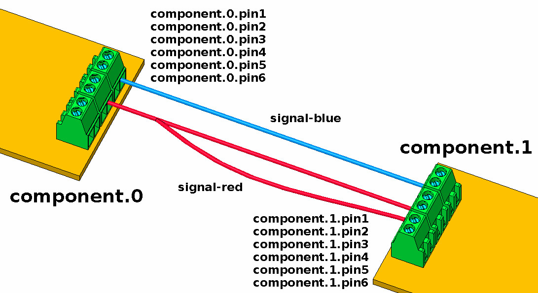
What you are writing about could be a suggestion for more pictures. In this first picture I just wanted to show what is component, pin, signal + parameter.
I would explain at maximum what the "net" command is.
Could you write me what you mean in HAL?
net signal-and2.0.in0 hm2_7i96.0.gpio.000.in => and2.0.in0
net signal-and2.0.in1 XXXXXX => and2.0.in1
net estop-signal and2.0.out => hm2_7i96.0.ssr.00.out-00
I would explain at maximum what the "net" command is.
Could you write me what you mean in HAL?
net signal-and2.0.in0 hm2_7i96.0.gpio.000.in => and2.0.in0
net signal-and2.0.in1 XXXXXX => and2.0.in1
net estop-signal and2.0.out => hm2_7i96.0.ssr.00.out-00
The following user(s) said Thank You: tommylight
Please Log in or Create an account to join the conversation.
- tommylight
-
- Away
- Moderator
-
Less
More
- Posts: 21708
- Thank you received: 7417
22 Apr 2020 14:03 #165104
by tommylight
Replied by tommylight on topic Quote illustration - for HAL
net e-stop-in and.0.in1
net x-limit and.0.in2
net and.0.out parport.0.pin1-out
Something like that
net x-limit and.0.in2
net and.0.out parport.0.pin1-out
Something like that
Please Log in or Create an account to join the conversation.
- tommylight
-
- Away
- Moderator
-
Less
More
- Posts: 21708
- Thank you received: 7417
22 Apr 2020 14:04 #165105
by tommylight
Replied by tommylight on topic Quote illustration - for HAL
That should also work.
net signal-and2.0.in0 hm2_7i96.0.gpio.000.in => and2.0.in0
net signal-and2.0.in1 XXXXXX => and2.0.in1
net estop-signal and2.0.out => hm2_7i96.0.ssr.00.out-00
Please Log in or Create an account to join the conversation.
- cmorley
- Offline
- Moderator
-
Less
More
- Posts: 7338
- Thank you received: 2162
25 Apr 2020 01:37 #165467
by cmorley
Replied by cmorley on topic Quote illustration - for HAL
I very much like your illustration, I think it quickly shows the HAL concept.
I would like to incorporate it in the manual.
But i wonder if you could change the text a bit.
component.0.pin0-out, component.0.pin1-out etc
component.1.pin0-in, component.0.pin1-in etc
Would be clearer of direction.
Also aligning the pin names with the connectors would be clearer too.
I'm thinking component.0.pin0.out on the left side of the comp 0 's connector and component.1.pin0.in on the right side of comp 1's connector (aligned with each screw terminal)
I hope I'm being clear enough.
The following user(s) said Thank You: tommylight
Please Log in or Create an account to join the conversation.
Moderators: HansU
Time to create page: 0.185 seconds