Changing trajectory planner mode within same file?
- MJG
- Offline
- New Member
-

Less
More
- Posts: 4
- Thank you received: 0
09 Mar 2014 10:00 #44591
by MJG
Changing trajectory planner mode within same file? was created by MJG
I have a model that requires a high degree of positional accuracy on some parts. So I'm using G61 and am happy with the results.
However, for those areas where the toolpath is simply removing stock from the model, I am happy to sacrifice XY accuracy for speed. So, something like G64 P0.2 would probably be ok.
I just don't know how to specify this changeover in my g-code.
I have tried manually entering G64 P0.2 while the machine is midway through a job (started with G61) but I just get an error message - something about the mode being set to "auto" and the interpreter not being "idle".
Is what I am asking not possible? Or is there a way to change modes while keeping the spindle running?
Cheers,
Matthew
Please Log in or Create an account to join the conversation.
- ArcEye
- Offline
- Junior Member
-

Less
More
- Posts: 25
- Thank you received: 758
09 Mar 2014 14:34 #44592
by ArcEye
Replied by ArcEye on topic Changing trajectory planner mode within same file?
Hi
There are ways to execute MDI commands whilst a program is paused, but generally you can't and will get that error.
You presumably know at what stage you want to change path modes, what happens if you insert the change into your gcode at that point?
regards
There are ways to execute MDI commands whilst a program is paused, but generally you can't and will get that error.
You presumably know at what stage you want to change path modes, what happens if you insert the change into your gcode at that point?
regards
Please Log in or Create an account to join the conversation.
- ArcEye
- Offline
- Junior Member
-
Less
More
- Posts: 25
- Thank you received: 758
09 Mar 2014 17:28 #44595
by ArcEye
Replied by ArcEye on topic Changing trajectory planner mode within same file?
Hi again,
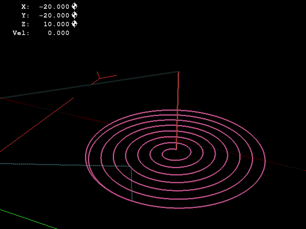
The gcode below cuts a circular recess into a flat surface.
It is not anything like what you are doing, but I chose it because the effect of path blending is very stark when talking about circles.
Half way through the code I changed the path mode to G64 P0.002 (it is imperial code)
The resultant plot is as normal, hard to see if the path mode changed
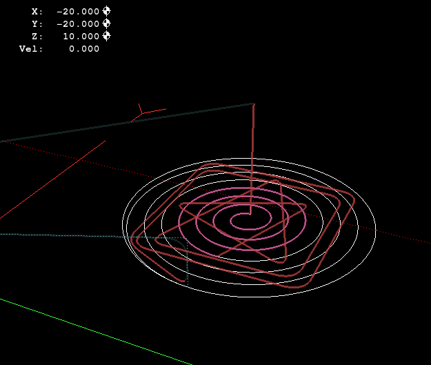
Change the mode to G64 P0.2 and you can see it definately did change, it is so far off the path, it cuts triangles and squares
(I assume you are using metric, as I normally do, so P0.2 is quite a reasonable value , rather than 2/10s of an inch which this represents )
)
So changing mode within your gcode works fine and that is the best way to do it.
A MDI command will fail if Linuxcnc is in AUTO or MANUAL mode.
As I said there are ways to pause and drop out of auto mode do something, go back to auto mode and resume, but that is quite an advanced programming subject.
What you want to do can be easily achieved by inserting path mode changes at relevant roughing out sections and reverting to G61 when doing the finishing stuff.
regards
The gcode below cuts a circular recess into a flat surface.
It is not anything like what you are doing, but I chose it because the effect of path blending is very stark when talking about circles.
G40 G90
G20 G17
G40 G8
G61
F3000
;M3 S600
;G4 P10
;M5
G00 X0.7500 Y0.7700
G01 Z-0.0300
G03X0.7000Y0.7200I0.0000J-0.0500
X0.7500Y0.6700I0.0500J0.0000
X0.8300Y0.7500I0.0000J0.0800
X0.7500Y0.8300I-0.0800J0.0000
X0.6400Y0.7200I0.0000J-0.1100
X0.7500Y0.6100I0.1100J0.0000
X0.8900Y0.7500I0.0000J0.1400
X0.7500Y0.8900I-0.1400J0.0000
X0.5800Y0.7200I0.0000J-0.1700
X0.7500Y0.5500I0.1700J0.0000
X0.9500Y0.7500I0.0000J0.2000
X0.7500Y0.9500I-0.2000J0.0000
X0.5200Y0.7200I0.0000J-0.2300
X0.7500Y0.4900I0.2300J0.0000
G64 P0.002
X1.0100Y0.7500I0.0000J0.2600
X0.7500Y1.0100I-0.2600J0.0000
X0.4600Y0.7200I0.0000J-0.2900
X0.7500Y0.4300I0.2900J0.0000
X1.0700Y0.7500I0.0000J0.3200
X0.7500Y1.0700I-0.3200J0.0000
X0.4000Y0.7200I0.0000J-0.3500
X0.7500Y0.3700I0.3500J0.0000
X1.1300Y0.7500I0.0000J0.3800
X0.7500Y1.1300I-0.3800J0.0000
X0.3400Y0.7200I0.0000J-0.4100
X0.7500Y0.3100I0.4100J0.0000
X1.1900Y0.7500I0.0000J0.4400
X0.7500Y1.1900I-0.4400J0.0000
X0.3100Y0.7500I0.0000J-0.4400
X0.7362Y0.3102I0.4400J0.0000
G00Z0.1500
G00X0.0Y0.0
G28
M2
Half way through the code I changed the path mode to G64 P0.002 (it is imperial code)
The resultant plot is as normal, hard to see if the path mode changed
Change the mode to G64 P0.2 and you can see it definately did change, it is so far off the path, it cuts triangles and squares
(I assume you are using metric, as I normally do, so P0.2 is quite a reasonable value , rather than 2/10s of an inch which this represents
)
So changing mode within your gcode works fine and that is the best way to do it.
A MDI command will fail if Linuxcnc is in AUTO or MANUAL mode.
As I said there are ways to pause and drop out of auto mode do something, go back to auto mode and resume, but that is quite an advanced programming subject.
What you want to do can be easily achieved by inserting path mode changes at relevant roughing out sections and reverting to G61 when doing the finishing stuff.
regards
The following user(s) said Thank You: MJG
Please Log in or Create an account to join the conversation.
- MJG
- Offline
- New Member
-
Less
More
- Posts: 4
- Thank you received: 0
10 Mar 2014 07:46 #44618
by MJG
Replied by MJG on topic Changing trajectory planner mode within same file?
Changing from G61 to G64 px.xx worked as you suggested.
Thanks a lot. I didn't realize it was that simple!
Cheers
Thanks a lot. I didn't realize it was that simple!
Cheers
Please Log in or Create an account to join the conversation.
Time to create page: 0.098 seconds