Fighting the PID!
- JohnnyCNC
-
 Topic Author
- Offline
- Platinum Member
-

Less
More
- Posts: 572
- Thank you received: 112
06 Mar 2018 01:58 - 06 Mar 2018 01:59 #107011
by JohnnyCNC
Fighting the PID! was created by JohnnyCNC
Hi Folks,
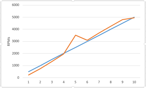
Well I am at that point where I have the spindle speed somewhat controlled by LinuxCNC. I have a 7i76 connected to a Sieg X3 mill which uses a 0-10v control. I have a reflective sensor on the spindle for the encoder feed back. I followed PCW's advice and removed the resistor from the wiper connection (TB4-2) and got the spindle enable connected to the XMT control board in the X3 and that is now working. I have been playing with the spindle parameters and testing. Below are the commanded RPMs / Actual RPMs / Voltage at each 500 RPM increment. This data was gathered with the PID turned off.
Next I turned the PID on and did some testing. At 2000~3000 RPM it will hold the speed really well for about 20 seconds then its as if the power drops out for a spit second. At startup If I command it to go 2000 or 3000 it will overshoot by 800~1000 then drop below and the come back up to speed. It does all this in about 2 to 4 seconds. At 1000 RPMs commanded its is as if the speed control is constantly being blipped every couple of seconds.
At this point I think if I could just remap the commanded speed output given a desired speed I would be happy with that. I think lincurve is what I need but I haven't figured out how to use it yet. On the other hand it feels like I might be close to getting the PID to work which would be the best.
I picked up some controls from a guy on youtube that allow the PID values to be entered real-time rather than changing the .ini and restarting LinuxCNC but I haven't tried to install them yet.
CMD Actual Diff Volts V-Diff
500 234 266 0.98 0.98
1000 751 249 1.94 0.96
1500 1347 153 2.96 1.01
2000 1951 49 3.97 1.02
2500 3527 -1027 4.97 1.00
3000 3105 -105 6.00 1.03
3500 3678 -178 7.02 1.02
4000 4251 -251 8.05 1.03
4500 4808 -308 9.09 1.04
5000 4957 43 10.12 1.03
On this graph the blue line is the commanded RPM and the orange is the actual RPM.
Could I really be close to getting the PID to work? If so what should I try next?
Does anyone have an example of using lincure?
At some point I want to do rigid tapping but I'll need to add a spindle encoder for that. I am also considering replacing the motor with a servo motor and a belt drive.
Here are my .ini and .hal data.
[SPINDLE_9]
P = .0002
I = 2
D = 0
FF0 = 1.0
FF1 = 0.5
FF2 = 0.00
BIAS = 0.0
DEADBAND = 0.0
MAX_OUTPUT = 5000.0
OUTPUT_MIN_LIMIT = 500
OUTPUT_MAX_LIMIT = 5000
OUTPUT_SCALE = 6200
#*******************
# SPINDLE S
#*******************
setp pid.s.Pgain [SPINDLE_9]P
setp pid.s.Igain [SPINDLE_9]I
setp pid.s.Dgain [SPINDLE_9]D
setp pid.s.bias [SPINDLE_9]BIAS
setp pid.s.FF0 [SPINDLE_9]FF0
setp pid.s.FF1 [SPINDLE_9]FF1
setp pid.s.FF2 [SPINDLE_9]FF2
setp pid.s.deadband [SPINDLE_9]DEADBAND
setp pid.s.maxoutput [SPINDLE_9]MAX_OUTPUT
setp pid.s.error-previous-target true
net spindle-index-enable <=> pid.s.index-enable
net spindle-enable => pid.s.enable hm2_5i25.0.7i76.0.0.spinena
net spindle-vel-cmd-rpm-abs => pid.s.command
net spindle-fb-rpm-abs => pid.s.feedback
net spindle-output <= pid.s.output
# ---digital potentionmeter output signals/setup---
setp hm2_5i25.0.7i76.0.0.spinout-minlim [SPINDLE_9]OUTPUT_MIN_LIMIT
setp hm2_5i25.0.7i76.0.0.spinout-maxlim [SPINDLE_9]OUTPUT_MAX_LIMIT
setp hm2_5i25.0.7i76.0.0.spinout-scalemax [SPINDLE_9]OUTPUT_SCALE
#setp hm2_5i25.0.encoder.00.scale [SPINDLE_9]ENCODER_SCALE
net spindle-output => hm2_5i25.0.7i76.0.0.spinout
net spindle-ccw => hm2_5i25.0.7i76.0.0.spindir
# ---setup spindle control signals---
net spindle-vel-cmd-rps <= motion.spindle-speed-out-rps
net spindle-vel-cmd-rps-abs <= motion.spindle-speed-out-rps-abs
net spindle-vel-cmd-rpm <= motion.spindle-speed-out
net spindle-vel-cmd-rpm-abs <= motion.spindle-speed-out-abs
net spindle-enable <= motion.spindle-on
net spindle-cw <= motion.spindle-forward
net spindle-ccw <= motion.spindle-reverse
net spindle-brake <= motion.spindle-brake
net spindle-revs => motion.spindle-revs
net spindle-at-speed => motion.spindle-at-speed
net spindle-vel-fb-rps => motion.spindle-speed-in
net spindle-index-enable <=> motion.spindle-index-enable
# ---Setup spindle at speed signals---
net spindle-vel-cmd-rpm-abs => near.0.in1
net spindle-fb-rpm-abs => near.0.in2
net spindle-at-speed motion.spindle-at-speed <= near.0.out
setp near.0.scale 1.04
# Use ACTUAL spindle velocity from spindle encoder
# spindle-velocity bounces around so we filter it with lowpass
# spindle-velocity is signed so we use absolute component to remove sign
# ACTUAL velocity is in RPS not RPM so we scale it.
setp scale.0.gain 60
setp lowpass.0.gain 1.1
net spindle-vel-fb-rps hm2_5i25.0.encoder.00.velocity => scale.0.in
net spindle-fb-rpm scale.0.out => abs.0.in
net spindle-fb-rpm-abs abs.0.out => lowpass.0.in
net spindle-fb-rpm-abs-filtered lowpass.0.out
Thanks
John
Last edit: 06 Mar 2018 01:59 by JohnnyCNC.
Please Log in or Create an account to join the conversation.
- andypugh
-

- Offline
- Moderator
-

Less
More
- Posts: 19875
- Thank you received: 4642
06 Mar 2018 12:40 #107030
by andypugh
Replied by andypugh on topic Fighting the PID!
If the graph is accurate then PID will never be able to work. You have an area where more-command = less-speed. PID controllers are too dumb to cope with that, they need a monotonic (but not necessarily linear) response function.
Have you tested the output voltage of the electronic potentiometer (Be very, very, careful, you are measuring a difference of 10V on pins that might be 120V above GND)
Have you tested the output voltage of the electronic potentiometer (Be very, very, careful, you are measuring a difference of 10V on pins that might be 120V above GND)
Please Log in or Create an account to join the conversation.
- JohnnyCNC
-
Topic Author
- Offline
- Platinum Member
-
Less
More
- Posts: 572
- Thank you received: 112
06 Mar 2018 15:32 #107038
by JohnnyCNC
Replied by JohnnyCNC on topic Fighting the PID!
I have measured the voltage across TB4-1 & TB4-3 and it was like 12.11volts after I added the wall wart per PCW's suggestion because there was not enough current coming from the speed control card in the mill. The speed stops increasing once the voltage gets to 10 volt mark so I limited the command to that point. Last night I found a documentation page on lincurve so I will try implementing that. I would be happy for now if the RPM went to and stayed somewhat close (+/- 50 RPM) to the commanded speed.
From PCW:
"If you only have 2.94V power the 7I76Es spindle interface will not work.
This probably means the motor control will not supply the several mA of current that the
spindle interface requires.
You can possibly use an ISOLATED power supply (like a wall wart) but you have to be very careful
because its all live. Also some potentiometer controlled motor circuits ( especially SCR circuits )
simple cannot be controlled by a variable voltage. "
Thank You
John
Please Log in or Create an account to join the conversation.
- andypugh
-
- Offline
- Moderator
-
Less
More
- Posts: 19875
- Thank you received: 4642
06 Mar 2018 16:48 #107044
by andypugh
Replied by andypugh on topic Fighting the PID!
My question was whether the control voltage varied smoothly with speed command, or whether that kick in the graph corresponded to a control voltage quirk.
Please Log in or Create an account to join the conversation.
- JohnnyCNC
-
Topic Author
- Offline
- Platinum Member
-
Less
More
- Posts: 572
- Thank you received: 112
06 Mar 2018 18:27 #107051
by JohnnyCNC
Replied by JohnnyCNC on topic Fighting the PID!
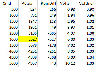
I looked at the chart again and it looks like I likely transposed two of the Actual rpm readings when I entered them into the spreadsheet.
I think this is how the chart should have looked but I'll have to confirm when I get home. The suspect values are highlighted. There is still a bump but its not so big. I am also going to rerun the test in 100 rpm increments at least for the area of the bump 1500-3500.

Thanks
John
I think this is how the chart should have looked but I'll have to confirm when I get home. The suspect values are highlighted. There is still a bump but its not so big. I am also going to rerun the test in 100 rpm increments at least for the area of the bump 1500-3500.
Thanks
John
Please Log in or Create an account to join the conversation.
- andypugh
-
- Offline
- Moderator
-
Less
More
- Posts: 19875
- Thank you received: 4642
06 Mar 2018 18:34 #107052
by andypugh
Replied by andypugh on topic Fighting the PID!
OK, either lincurve or PID ought to be able to cope with that.
I would probably use lincurve because spindle rpm isn't actually _that_ important.
It needs to be right, but "right" isn't something that you know as a number, but by result.
I would probably use lincurve because spindle rpm isn't actually _that_ important.
It needs to be right, but "right" isn't something that you know as a number, but by result.
Please Log in or Create an account to join the conversation.
- JohnnyCNC
-
Topic Author
- Offline
- Platinum Member
-
Less
More
- Posts: 572
- Thank you received: 112
06 Mar 2018 20:11 #107054
by JohnnyCNC
Replied by JohnnyCNC on topic Fighting the PID!
Thanks Andy,
I'll probably end up using lincurve but I think I'll play with the PID a little bit more just for the education. Do you think it would help if the PID was working with RPS rather than RPM since it is a more granular value?
Thanks
John
I'll probably end up using lincurve but I think I'll play with the PID a little bit more just for the education. Do you think it would help if the PID was working with RPS rather than RPM since it is a more granular value?
Thanks
John
Please Log in or Create an account to join the conversation.
- andypugh
-
- Offline
- Moderator
-
Less
More
- Posts: 19875
- Thank you received: 4642
06 Mar 2018 20:15 #107055
by andypugh
Replied by andypugh on topic Fighting the PID!
No, it's all floating point so the absolute value is irrelevant.
Please Log in or Create an account to join the conversation.
- andypugh
-
- Offline
- Moderator
-
Less
More
- Posts: 19875
- Thank you received: 4642
06 Mar 2018 20:18 #107057
by andypugh
Replied by andypugh on topic Fighting the PID!
Try the PID with FF1 set to zero.
In fact set all the terms to zero and adjust FF0 until you get one specific speed correct, than add a bit of I to bring the others in.
FF0 of 1 will be correct if the analogue output is scaled correctly, though.
In fact set all the terms to zero and adjust FF0 until you get one specific speed correct, than add a bit of I to bring the others in.
FF0 of 1 will be correct if the analogue output is scaled correctly, though.
Please Log in or Create an account to join the conversation.
- JohnnyCNC
-
Topic Author
- Offline
- Platinum Member
-
Less
More
- Posts: 572
- Thank you received: 112
06 Mar 2018 23:34 #107061
by JohnnyCNC
Replied by JohnnyCNC on topic Fighting the PID!
Andy, I'll try the PID setting next. Thanks
I reran my test using 100 rpm increments and a better meter. The results look better.
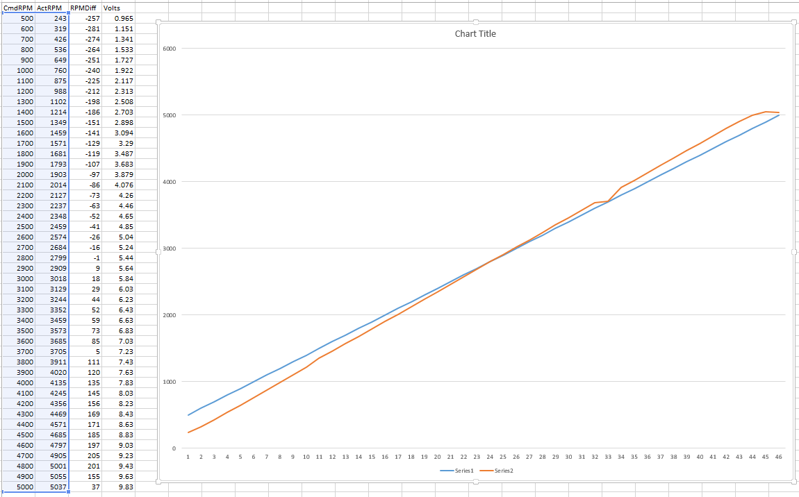
John
I reran my test using 100 rpm increments and a better meter. The results look better.
John
Please Log in or Create an account to join the conversation.
Time to create page: 0.243 seconds