Request G6, Ellipse and G7, bezier curve
- Grotius
-
 Topic Author
- Offline
- Platinum Member
-

Less
More
- Posts: 2419
- Thank you received: 2348
11 Jun 2020 17:33 - 11 Jun 2020 17:38 #171153
by Grotius
Replied by Grotius on topic Request G6, Ellipse and G7, bezier curve
Hi,
Rodw wrote :
I think the new G code will need to align with an existing gcode flavour so that there is post processor support.
Check the next proposal, let me know how you think about it.
If you like it. I can dig into the source code of linuxcnc, and make a template in 5 minutes
Gcode format proposal for natural cubic splines, bezier curves and ellipse.
Existing G formats:
G5 Cubic Spline
G5.1 Quadratic Spline
G5.2 G5.3 NURBS Block
To integrate:
G5.4 G5.5 Natural cubic spline (spline trough points, used in Inkscape and Freecad dxf outputs)
G5.6 G5.7 Bezier curve
G5.8 Ellipse cw
G5.9 Ellipse ccw
G5.10 Motion Interpolation Template MIT.
Why a G5.4 and a G5.5 block for one spline?
It's the same setup as Nurbs, we use a start-block and a end-block.
Example :
G0 X0 Y0 (start of the spline)
F1500
G5.4 (start block)
X10 Y10 (first control point)
X100 Y100 (second control point)
X250 Y25 (etc)
X350 Y-20
X600 Y0
G5.5 (end block)
The same format is for bezier curve :
G0 X0 Y0
F1500
G5.6 P1 L3 (start block)
X0 Y0
X0 Y100
X100 Y100
X100 Y0
G5.7 (end block)
(mention, if a 5fth point is attached to the bezier curve, we can expand the to a 4th degree bezier curve later on, you see i am
an optimist") ).
).
Ellipse cw:
G0 X0 Y0
F1500
G5.8 X50 Y50 I20 J20 (clockwise cw)
Ellipse ccw:
G0 X0 Y0
F1500
G5.9 X50 Y50 I20 J20 (counter_clockwise ccw)
For ellipse i like to add the following letter packs into the gcode intepreter:
RA = ratio
PS = pi start angle
PE = pi end angle
I = center_x - start_x, J = center_y - start_y, in line with G2, G3, etc.
Added c++ functions for natural cubic spline, bezier curve and ellipse.
Rodw wrote :
I think the new G code will need to align with an existing gcode flavour so that there is post processor support.
Check the next proposal, let me know how you think about it.
If you like it. I can dig into the source code of linuxcnc, and make a template in 5 minutes
Gcode format proposal for natural cubic splines, bezier curves and ellipse.
Existing G formats:
G5 Cubic Spline
G5.1 Quadratic Spline
G5.2 G5.3 NURBS Block
To integrate:
G5.4 G5.5 Natural cubic spline (spline trough points, used in Inkscape and Freecad dxf outputs)
G5.6 G5.7 Bezier curve
G5.8 Ellipse cw
G5.9 Ellipse ccw
G5.10 Motion Interpolation Template MIT.
Why a G5.4 and a G5.5 block for one spline?
It's the same setup as Nurbs, we use a start-block and a end-block.
Example :
G0 X0 Y0 (start of the spline)
F1500
G5.4 (start block)
X10 Y10 (first control point)
X100 Y100 (second control point)
X250 Y25 (etc)
X350 Y-20
X600 Y0
G5.5 (end block)
The same format is for bezier curve :
G0 X0 Y0
F1500
G5.6 P1 L3 (start block)
X0 Y0
X0 Y100
X100 Y100
X100 Y0
G5.7 (end block)
(mention, if a 5fth point is attached to the bezier curve, we can expand the to a 4th degree bezier curve later on, you see i am
an optimist
).Ellipse cw:
G0 X0 Y0
F1500
G5.8 X50 Y50 I20 J20 (clockwise cw)
Ellipse ccw:
G0 X0 Y0
F1500
G5.9 X50 Y50 I20 J20 (counter_clockwise ccw)
For ellipse i like to add the following letter packs into the gcode intepreter:
RA = ratio
PS = pi start angle
PE = pi end angle
I = center_x - start_x, J = center_y - start_y, in line with G2, G3, etc.
Added c++ functions for natural cubic spline, bezier curve and ellipse.
Last edit: 11 Jun 2020 17:38 by Grotius.
The following user(s) said Thank You: phillc54, tommylight, Aciera
Please Log in or Create an account to join the conversation.
- Grotius
-
Topic Author
- Offline
- Platinum Member
-
Less
More
- Posts: 2419
- Thank you received: 2348
12 Jun 2020 13:47 - 12 Jun 2020 17:25 #171252
by Grotius
Replied by Grotius on topic Request G6, Ellipse and G7, bezier curve
Hi,
I was curious if G41 & G42 Cutter Compensation could be used with the new spline interpolation.
If we use a code like this :
G41.1 D10 (Dynamic Cutter Compensation on, left of programmed path)
G0 X0 Y0 (start of the spline)
F1500
G5.4 (start block)
X10 Y10 (first control point)
X100 Y100 (second control point)
X250 Y25 (etc)
X350 Y-20
X600 Y0
G5.5 (end block)
G40 (tool compensation off)
The red dots are controlpoints. Their offset is calculated at a precision of 0.001mm for each offsetted controlpoint.
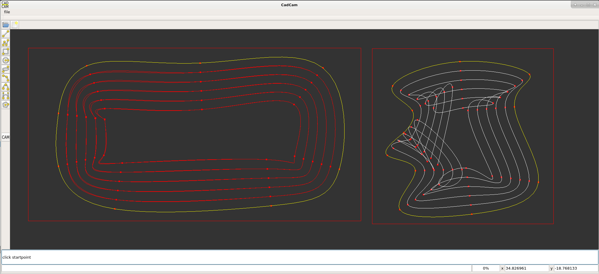
At the left you see double path's in red. This is visible when zooming in the picture.
This is a preview if a spline is played from left to right and visa versa.
So important is, when changing the contour direction for a spline from cw to ccw, interpolate the spline backwards.
About the tool radius compensation, the solution for this problem is quite simple.
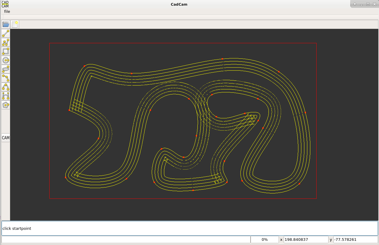
If the machine has a active tool compensation, we interpolate the spline as an offset linestrip.
For this linestrip i will make a interpolation model, that we can use to get it right.
The linestrip has to have a clean up function, when the lines are becoming less 0mm, they must be deleted and re-attached.
Okey so far so good !
Update:
This is a spline_offset_as_linestrip. This is good. What we miss is a line-line interection to reconnect the offset path's.
For pockets we do a contour self intersect check, but that has nothing to do with this.
I was curious if G41 & G42 Cutter Compensation could be used with the new spline interpolation.
If we use a code like this :
G41.1 D10 (Dynamic Cutter Compensation on, left of programmed path)
G0 X0 Y0 (start of the spline)
F1500
G5.4 (start block)
X10 Y10 (first control point)
X100 Y100 (second control point)
X250 Y25 (etc)
X350 Y-20
X600 Y0
G5.5 (end block)
G40 (tool compensation off)
The red dots are controlpoints. Their offset is calculated at a precision of 0.001mm for each offsetted controlpoint.
At the left you see double path's in red. This is visible when zooming in the picture.
This is a preview if a spline is played from left to right and visa versa.
So important is, when changing the contour direction for a spline from cw to ccw, interpolate the spline backwards.
About the tool radius compensation, the solution for this problem is quite simple.
If the machine has a active tool compensation, we interpolate the spline as an offset linestrip.
For this linestrip i will make a interpolation model, that we can use to get it right.
The linestrip has to have a clean up function, when the lines are becoming less 0mm, they must be deleted and re-attached.
Okey so far so good !
Update:
This is a spline_offset_as_linestrip. This is good. What we miss is a line-line interection to reconnect the offset path's.
For pockets we do a contour self intersect check, but that has nothing to do with this.
Attachments:
Last edit: 12 Jun 2020 17:25 by Grotius.
The following user(s) said Thank You: phillc54, tommylight, Aciera, bbsr_5a
Please Log in or Create an account to join the conversation.
- andypugh
-

- Offline
- Moderator
-

Less
More
- Posts: 19879
- Thank you received: 4643
28 Jun 2020 12:14 #172981
by andypugh
Given that a large proportion of CAM programs don't even support G2 and G3 arcs I think that this is optimistic.
LinuxCNC has had splines for 10 years or so, and in that time I have not heard of a single CAM system that uses them.
I think that the same would be true of bezier and ellipse. I don't think that they are a bad idea, per-se, but I don't think that they would attract support from the CAM vendors.
And you might be able to have G6, but G7 already exists. (lathe diameter mode). G6 seems to be either "parabolic" or "spline" on the controls that use it.
Replied by andypugh on topic Request G6, Ellipse and G7, bezier curve
The power of
a G6 and G7 output is that the cam program does not have to facetate a ellipse into a fragmented linestrip. This results in
thousand lines of code when the cam program's calculate a very accurate cnc path.
Given that a large proportion of CAM programs don't even support G2 and G3 arcs I think that this is optimistic.
LinuxCNC has had splines for 10 years or so, and in that time I have not heard of a single CAM system that uses them.
I think that the same would be true of bezier and ellipse. I don't think that they are a bad idea, per-se, but I don't think that they would attract support from the CAM vendors.
And you might be able to have G6, but G7 already exists. (lathe diameter mode). G6 seems to be either "parabolic" or "spline" on the controls that use it.
The following user(s) said Thank You: tommylight, rodw
Please Log in or Create an account to join the conversation.
- jurod
-

- Offline
- Senior Member
-

Less
More
- Posts: 68
- Thank you received: 6
09 Mar 2021 08:21 #201525
by jurod
Replied by jurod on topic Request G6, Ellipse and G7, bezier curve
The G5.4 gcode function would help me a lot.
Using the "position recording" program from BigJohnT forum.linuxcnc.org/21-axis/30986-axis-po...gger?start=20#201523
i will create a lot of points. Then I want to put these points connect to splines.
How to integrate your G5.4 into LC?
Using the "position recording" program from BigJohnT forum.linuxcnc.org/21-axis/30986-axis-po...gger?start=20#201523
i will create a lot of points. Then I want to put these points connect to splines.
How to integrate your G5.4 into LC?
Please Log in or Create an account to join the conversation.
- lrak
-

- Offline
- Premium Member
-

Less
More
- Posts: 114
- Thank you received: 22
15 Mar 2021 05:42 #202305
by lrak
Replied by lrak on topic Request G6, Ellipse and G7, bezier curve
@jurod
I think I understand what you are after. I've used a few programs that take points (in the form of a B&W png file) and converts them in svg ( where curves are done with splines). The software is fussy about the details of the PNG file - but it basically works.
The result is a much smaller file if things are working right.
I can imagine that the lack of spline support in CAM programs might change as time goes on. 3D CAD software that uses splines can be much easier to use for blending curves - chamfered corners are better as splines. But does it matter if the G-code uses them?
Please Log in or Create an account to join the conversation.
- jurod
-
- Offline
- Senior Member
-
Less
More
- Posts: 68
- Thank you received: 6
15 Mar 2021 07:16 #202309
by jurod
Replied by jurod on topic Request G6, Ellipse and G7, bezier curve
The problem is that I can't use any CAM CAD on the machine.
Please Log in or Create an account to join the conversation.
- jurod
-
- Offline
- Senior Member
-
Less
More
- Posts: 68
- Thank you received: 6
22 Mar 2021 05:45 #203203
by jurod
Replied by jurod on topic Request G6, Ellipse and G7, bezier curve
Can anyone write in PYTHONE remap Gcode for bezier curve?
Please Log in or Create an account to join the conversation.
- andypugh
-
- Offline
- Moderator
-
Less
More
- Posts: 19879
- Thank you received: 4643
23 Mar 2021 00:35 #203321
by andypugh
I don't think that is possible. Any curves have to be calculated in the trajectory planner.
What might be informative would be to look at the commit that introduced splines.
github.com/LinuxCNC/linuxcnc/commit/3cef...72112ea60d6a633b61ec
Some of it is just demos and such, but the magic is in interp_convert.cc, gcodemodule.cc and emccanon.cc
Replied by andypugh on topic Request G6, Ellipse and G7, bezier curve
Can anyone write in PYTHONE remap Gcode for bezier curve?
I don't think that is possible. Any curves have to be calculated in the trajectory planner.
What might be informative would be to look at the commit that introduced splines.
github.com/LinuxCNC/linuxcnc/commit/3cef...72112ea60d6a633b61ec
Some of it is just demos and such, but the magic is in interp_convert.cc, gcodemodule.cc and emccanon.cc
Please Log in or Create an account to join the conversation.
- newbynobi
-
- Offline
- Platinum Member
-
Less
More
- Posts: 1931
- Thank you received: 394
23 Mar 2021 05:33 #203351
by newbynobi
Replied by newbynobi on topic Request G6, Ellipse and G7, bezier curve
I would think it is possible to write a remap for the calculation in python.
That remap will not be able to do the trajectory planer work, but could fade the planer witch information of point to point strait movement, so return G1 moves. depending on the curve and the distance between the points that might give a lot of information. At the end each movement is just a movement between to points.
As basis numpy and mathplot can be a possibility.
Norbert
Please Log in or Create an account to join the conversation.
- andypugh
-
- Offline
- Moderator
-
Less
More
- Posts: 19879
- Thank you received: 4643
23 Mar 2021 09:40 #203367
by andypugh
Replied by andypugh on topic Request G6, Ellipse and G7, bezier curve
Can an ellipse and a bezier be approximated with arcs, splines or NURBS?
Given that a reasonable approximation of an ellipse can be drawn with 4 arcs I think that is probably straightforward.
As cubic splines, quadratic splines and NURBS already exist in LinuxCNC G-code I think that re-mapping would potentially be an option for an ellipse. I am not sure about a Bezier.
math.stackexchange.com/questions/3333055...segment-and-b-spline
Suggests (to me) that it might be possible to construct a B-spline to match a given Bezier to within the required tolerance.
Please Log in or Create an account to join the conversation.
Time to create page: 0.265 seconds