

- Posts: 286
- Thank you received: 113
hobbing helical gear
6 years 1 month ago #181082
by CORBETT
Replied by CORBETT on topic hobbing helical gear
@Aciera
LOL, I have milked stones...
"After all there is no time like the present, is there?"
Yes I need a good push to get going with it... been trying to reduce some other projects so I can get this one started. Like everyone, way too many irons in the fire, LOL.
LOL, I have milked stones...
"After all there is no time like the present, is there?"
Yes I need a good push to get going with it... been trying to reduce some other projects so I can get this one started. Like everyone, way too many irons in the fire, LOL.
Please Log in or Create an account to join the conversation.

5 years 8 months ago #200010
by Ravi0000
Replied by Ravi0000 on topic hobbing helical gear
Hello everyone I m Ravi form India patna BIHAR
Making a cnc gear hobbing machine for helical gear cutting
Making a cnc gear hobbing machine for helical gear cutting
Please Log in or Create an account to join the conversation.

5 years 8 months ago #200066
by Aciera
Replied by Aciera on topic hobbing helical gear
Ah, another one.
So are you also refitting an older manual machine?
So are you also refitting an older manual machine?
Please Log in or Create an account to join the conversation.

5 years 8 months ago #200473
by andypugh
Unfortunately I was not really reading the forum when this was discussed.
I keep meaning to make a helical gear, but have not done so yet.
There are two things to do:
1) Angle the hob to the gear by the normal amount (hob lead angle) and by the helix angle
2) Add in an extra movement of the hob relative to the blank proportional to the distance travelled along the gear shaft axis.
Exactly how the maths works out will depend on the machine. On my mill the X feed direction swings with the table (which sets the hob angle), whereas on a conventional hobber I don't think that it does.
This second part could be done in two ways:
a) By rotating the blank by an extra amount. The problem here is that the extra amount depends on the radius of the cut
b) By shifting the hob along the hob axis. This should work at any radius (but I haven't analysed it, this is just visualising it). It has the advantage of evening the wear on the hob. It has the disadvantage that the hob might not actually be long enough.
b) Would be easy on my my milling-machine hobber, but might not even be an option on a real hobbing machine.
Both are equally easy in HAL. Just another scale and sum. You don't need to worry about the absolute position of the linear axis even, as the starting point will be in the numbers from the start.
If I was to make helical gears there would be a lot of nylon or wax practice parts made first, whilst I checked the maths.
Replied by andypugh on topic hobbing helical gear
Aciera wrote: I think I'll let Andy figure that out overnight and wait for him to present his solution (including a GUI).
Unfortunately I was not really reading the forum when this was discussed.
I keep meaning to make a helical gear, but have not done so yet.
There are two things to do:
1) Angle the hob to the gear by the normal amount (hob lead angle) and by the helix angle
2) Add in an extra movement of the hob relative to the blank proportional to the distance travelled along the gear shaft axis.
Exactly how the maths works out will depend on the machine. On my mill the X feed direction swings with the table (which sets the hob angle), whereas on a conventional hobber I don't think that it does.
This second part could be done in two ways:
a) By rotating the blank by an extra amount. The problem here is that the extra amount depends on the radius of the cut
b) By shifting the hob along the hob axis. This should work at any radius (but I haven't analysed it, this is just visualising it). It has the advantage of evening the wear on the hob. It has the disadvantage that the hob might not actually be long enough.
b) Would be easy on my my milling-machine hobber, but might not even be an option on a real hobbing machine.
Both are equally easy in HAL. Just another scale and sum. You don't need to worry about the absolute position of the linear axis even, as the starting point will be in the numbers from the start.
If I was to make helical gears there would be a lot of nylon or wax practice parts made first, whilst I checked the maths.
Please Log in or Create an account to join the conversation.
5 years 6 months ago - 5 years 6 months ago #206941
by timo
Replied by timo on topic hobbing helical gear
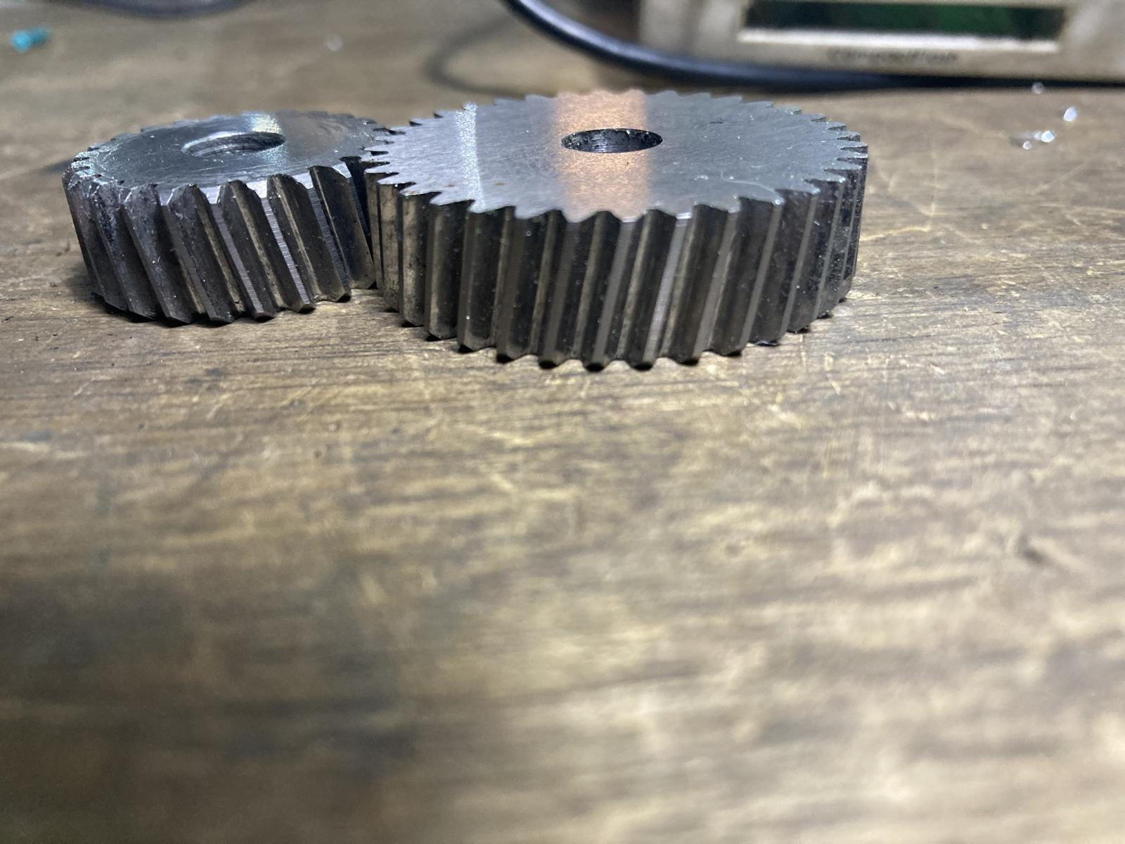
Hello all,
quite some time ago I tried this based on andies Youtube advise and forum information.
For not too steep helix angles with the hob it can be simply done ( on my machine to move the column down while traversing the hob ) As far as I recall it is not dependent on blank diameter, but as the hob is tilted the hob does not move along its axle, but slightly off.
Did not notice that yet.
I have experimented with rotation of the blank for that Andie suggested another scale and hooking it up to the x-position.
I am a little stuck with figuring out what numbers to put into the hal file.
Did someone get it running yet?
Greetings Timo
p.s. the gear were made shifting the hob. Problems why I am not happy with hob shifting.
The width of the gears will be limited to 10 or so mm, rotating the gear blank would allow thicker gears, or cutting more than one at a time.
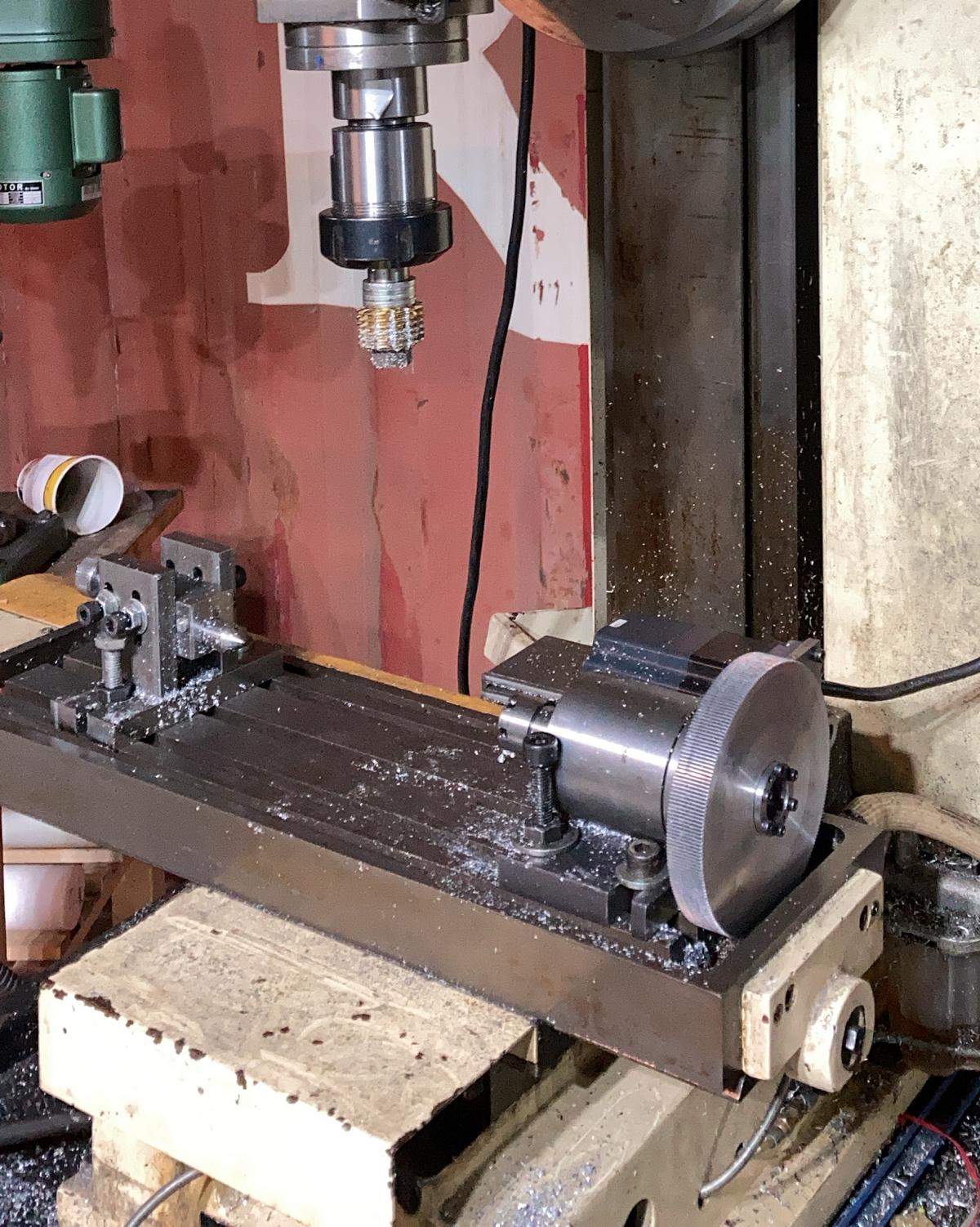
machine looks like this.
quite some time ago I tried this based on andies Youtube advise and forum information.
For not too steep helix angles with the hob it can be simply done ( on my machine to move the column down while traversing the hob ) As far as I recall it is not dependent on blank diameter, but as the hob is tilted the hob does not move along its axle, but slightly off.
Did not notice that yet.
I have experimented with rotation of the blank for that Andie suggested another scale and hooking it up to the x-position.
I am a little stuck with figuring out what numbers to put into the hal file.
Did someone get it running yet?
Greetings Timo
p.s. the gear were made shifting the hob. Problems why I am not happy with hob shifting.
The width of the gears will be limited to 10 or so mm, rotating the gear blank would allow thicker gears, or cutting more than one at a time.
machine looks like this.
Last edit: 5 years 6 months ago by timo. Reason: adding picture
The following user(s) said Thank You: tommylight, johnmc1
Please Log in or Create an account to join the conversation.

5 years 6 months ago #206960
by Henk
Replied by Henk on topic hobbing helical gear
On our Pfauter PE500 (running Linuxcnc) at work, the z axis is parallel to the work piece axis, which is on the C axis. The Y axis is parallel to the hob/spindle, so when you apply a hob shift or hob axial movement, the C axis must rotate by a corresponding amount, determined by the gear reference diameter and the angle of the B axis ( hob tilt axis).
When hobbing a helical gear, the Y axis generally stays in the same position, although it is possible to use axial feed as well to spread the wear across the hob. The Y axis or hob shift is not used to generate the helix angle though.
The Helix angle is generated by additional C axis movement linked to the Z axis (X in your case), this ratio is determined by the Lead of the gear being cut.
The last link that determines the C axis position, is the hob or spindle. this relationship is determined by the number of teeth on the job, and the number of hob starts.
These three relationships are summed, and the result drives the C axis position.
When hobbing a helical gear, the Y axis generally stays in the same position, although it is possible to use axial feed as well to spread the wear across the hob. The Y axis or hob shift is not used to generate the helix angle though.
The Helix angle is generated by additional C axis movement linked to the Z axis (X in your case), this ratio is determined by the Lead of the gear being cut.
The last link that determines the C axis position, is the hob or spindle. this relationship is determined by the number of teeth on the job, and the number of hob starts.
These three relationships are summed, and the result drives the C axis position.
The following user(s) said Thank You: johnmc1
Please Log in or Create an account to join the conversation.
Time to create page: 0.103 seconds