Renishaw TP-20 Probe Connection

More
5 years 6 months ago #204958 by jackdavies
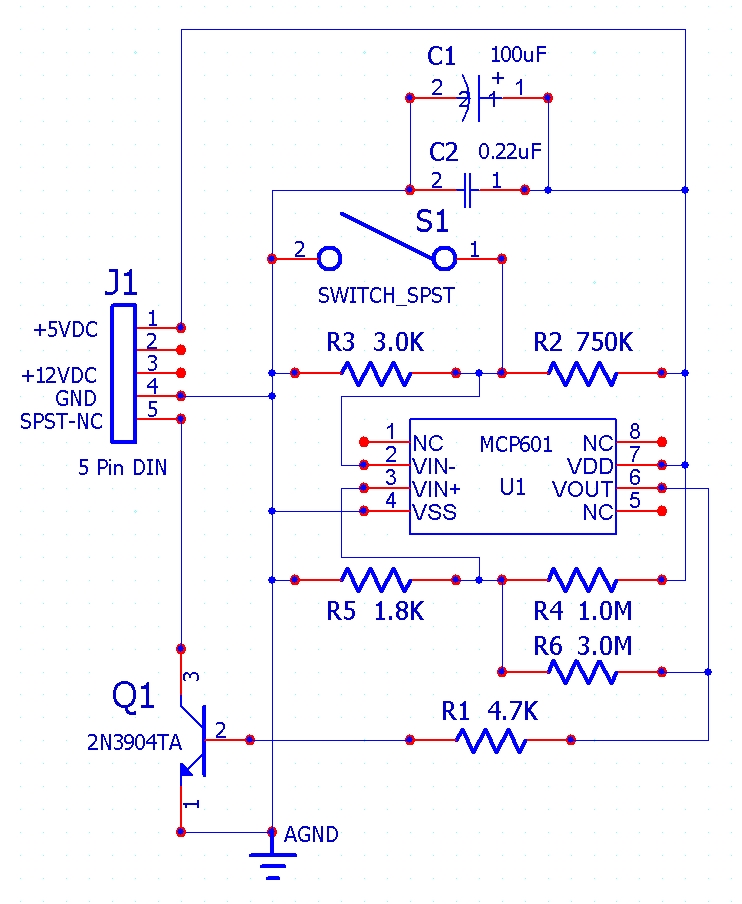
This is the non-inverting circuit diagram from the CNCZone post.

Please Log in or Create an account to join the conversation.
More
5 years 6 months ago #204984 by spumco
Of course my post was written pre-coffee. I meant increase in resistance as the probe triggers...

Duh.

Thanks for throwing up the diagram for future reference.

-R

Please Log in or Create an account to join the conversation.

More
5 years 6 months ago #205054 by jackdavies
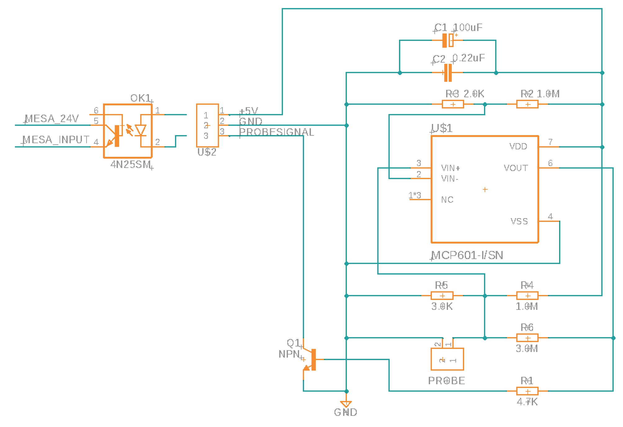
So I have redrawn the circuit so I can make some PCBs for this, but I am having trouble with the output voltage signal. I am using the inverting signal version of the circuit to be able to trigger the opto during a probe, otherwise the LED in the opto would be always on.

I am running my Mesa card at 24v field power, but this circuit operates on 5v so I thought about using an optocoupler to close the signal on the Mesa card for the PROBE IN pin. So I would power this from a 5v pin on the Mesa, but the actual triggering circuit would be separate.

Would something like this work?

Please Log in or Create an account to join the conversation.
More
5 years 6 months ago #205073 by jackdavies
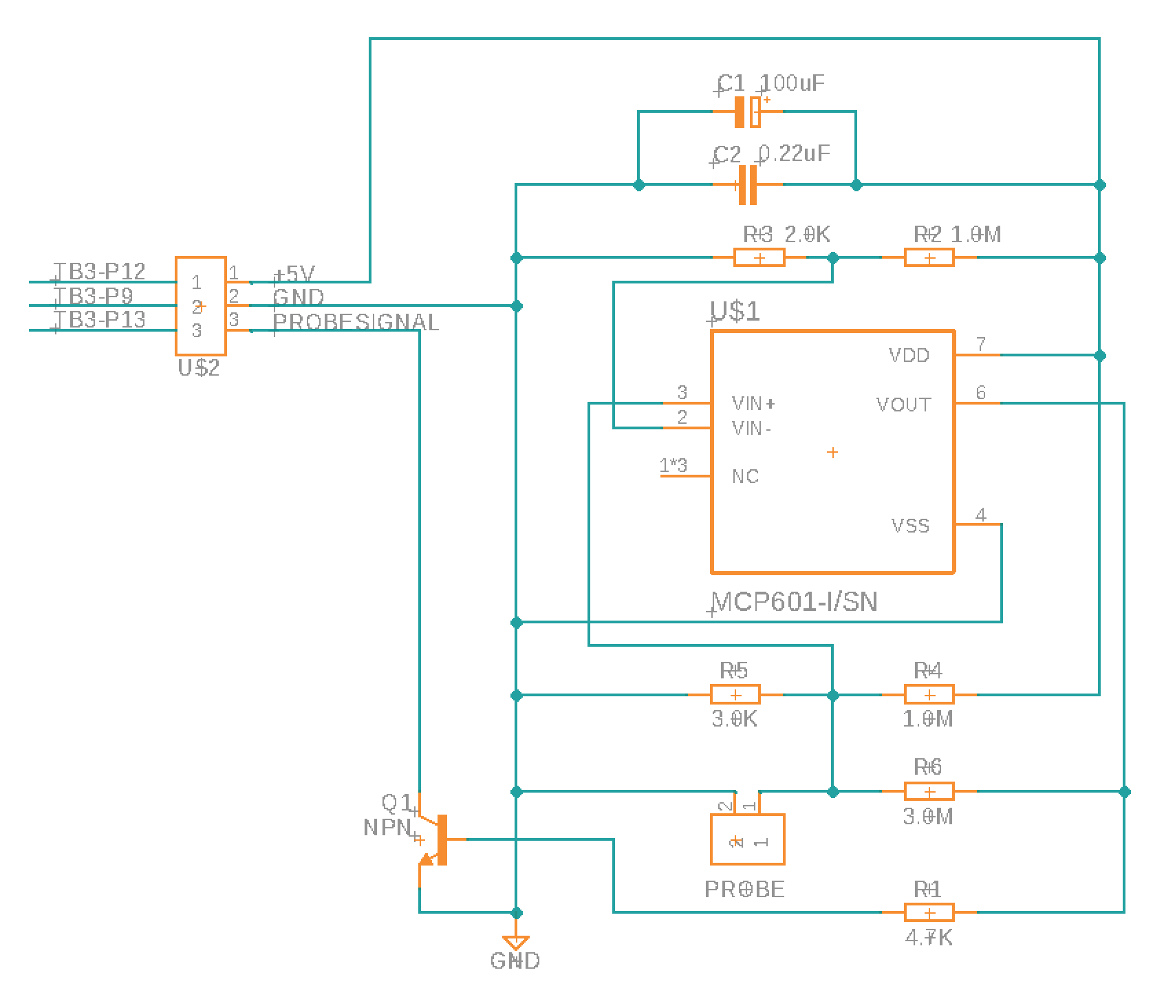
I think I could use the 5v Step/Dir for the supply and Enc Index in for the signal, as explained here - forum.linuxcnc.org/27-driver-boards/3668...stion?start=0#135209

Would then not need the optocoupler and simplify things and speed it up.

Please Log in or Create an account to join the conversation.

More
5 years 6 months ago #205074 by andypugh
I have a number of Zeiss probes that also have a significant resistance when closed.

I have forgotten what I did to make them work, quite possibly nothing at all.
500R is quite probably low enough to pull-down a pulled-up GPIO input. Have you tried just wiring it in to see what happens?

Now, if you can tell me how to interface a TP-200 probe....

Please Log in or Create an account to join the conversation.
More
5 years 6 months ago #205077 by jackdavies
I have not yet tried wiring it in, I am still waiting for some spring contacts to arrive, but yes maybe it will just work and I am over complicating this haha.

However there is a strong benefit of reducing the voltage and current actually applied to the ball and pins in the probe to prevent pitting of the contacts over time. As well as an improvement in trigger repeatability.

Can the Index signal at TB3-13 be used as a 5v input? I have put the connections in the attached schematic on the left.

Thanks!

Please Log in or Create an account to join the conversation.

Time to create page: 0.074 seconds
Powered by Kunena Forum