First steps for re-doing electrical
- rfrey
- Offline
- Junior Member
-

Less
More
- Posts: 20
- Thank you received: 3
03 May 2021 16:01 #207729
by rfrey
First steps for re-doing electrical was created by rfrey
Hi. Very rookie questions here! I have an early Novakon machine. When I bought it several years ago it ran on Mach3 but the owner had re-done some of the electronics to make them more compact. With the help of a friend I did a bodge job on it to convert it to LinuxCNC using a 5i25 and 7i76. It worked for several years but the built-in Estops don't work, it has no end stops, there are several wires I've traced that don't seem to do anything, and I don't really understand the electronics which bugs me.There are no wiring diagrams or schematics.
The motherboard gave out, and I have no projects in the works so I thought I'd I'd take the opportunity to beat back some of the entropy and also learn how to do this sort of thing correctly. I've got ambitions to add a pendant and maybe a spindle encoder, and I'd like to do that in a non-random-walk kinda way. My questions:
The motherboard gave out, and I have no projects in the works so I thought I'd I'd take the opportunity to beat back some of the entropy and also learn how to do this sort of thing correctly. I've got ambitions to add a pendant and maybe a spindle encoder, and I'd like to do that in a non-random-walk kinda way. My questions:
- My cursory web search suggests that most industrial machines use ladder diagrams, but the examples I saw were all from the 80s or earlier. Is that still good practice in 2021? Should I skip directly to a schematic or a wiring diagram?
- How do people like to document the HAL design? Is the code good enough, or would a "pro" do some advance design on paper first, and if so, what techniques are used? Ladder diagrams again?
- Is there a tutorial or introductory article on basic design for cnc electronics circuits, as basic as putting in an e-stop loop, where to put fuses, etc? I can copy existing designs but a HOWTO would be awesome if it exists.
- Is there common software that people like to use for the designs, or is a bic pen the best technology?
- Is this a terrible idea, and should I leave well enough alone?
Please Log in or Create an account to join the conversation.
- BeagleBrainz
-

- Visitor
-

03 May 2021 17:03 #207739
by BeagleBrainz
Replied by BeagleBrainz on topic First steps for re-doing electrical
In the middle to almost finished redoing the electrical myself.
Did everything in my head, but did check each section as I went along, rather than doing everything then hoping it would work.
Did cheat somewhat by designing a pcb to make wiring if the self holding relays easier.
Get a lot of bootlace ferrules and a decent crimper to make life easier.
If you want diagrams use whatever CAD package you feel comfortable with I guess.
Whichever way you do it, be neat & logical. It’s far easier to fault find when it’s all neat rather than a rat’s nest.
I guess designing everything in my head isn’t the most logical way to do it.
Please Log in or Create an account to join the conversation.
- nonspecialist
- Offline
- New Member
-

Less
More
- Posts: 2
- Thank you received: 0
03 May 2021 20:08 - 04 May 2021 22:24 #207746
by nonspecialist
Replied by nonspecialist on topic First steps for re-doing electrical
I`m also sorting a controller. After a fitful start I created a bill of materials at the same I time placed IEC symbols in a drawing. Listing every part number.For a rookie a bic pen is probably better than trying to do everything in ones head. I found a pdf called Example Standard Mill Electrical Drawing CNC CONTROL SYSTEM ELECTRICAL CIRCUIT DIAGRAM while searching for examples to follow. I found I could edit it in Linux`s Libra Office without having to start from scratch in Mechanical Desktop which not everyone has. I'm seeing more plans submitted in pdf format in professional settings so it might be an easy way to get started. The advantage of using graphics apps over pen and ink is being able to save and change as often as wanted and also being able to share it with anyone who might be willing to give advice. You can also include details about every part. Details found by doing search's for every part number. These part number lead to datasheets by way of understanding the electronics. I organize data sheets along the form of circuit paths / bill of materials. I don't wish to promote any particular supplier if that is considered spamming here. But understanding the electronics is greatly helped when the company behind your part numbers has excellent documentation. Even if you don't buy from them industrial automation equipment makers allow users to download guides. Some as basic as where to put fuses to overviews of control box layout including recommended parts.
Last edit: 04 May 2021 22:24 by nonspecialist. Reason: Assuming company names not allowed ?
Please Log in or Create an account to join the conversation.
- tommylight
-

- Away
- Moderator
-

Less
More
- Posts: 21747
- Thank you received: 7433
03 May 2021 21:46 #207749
by tommylight
Replied by tommylight on topic First steps for re-doing electrical
@nonspecialist
That is considered SPAM around here and it is frowned upon, vigorously !
That is considered SPAM around here and it is frowned upon, vigorously !
Please Log in or Create an account to join the conversation.
- rfrey
- Offline
- Junior Member
-
Less
More
- Posts: 20
- Thank you received: 3
04 May 2021 22:28 #207888
by rfrey
Replied by rfrey on topic First steps for re-doing electrical
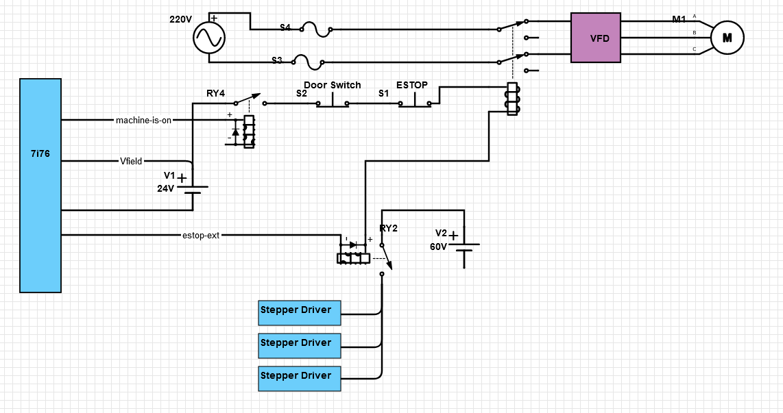
It seems like the e-stop circuit is the hardest, and if I get that I'll have it licked. That's probably naive but I'm going with it.
estop-ext will be tied into the estop-latch component that I've read about here, so that either the software or the hardware can trigger the estop, but if it's triggered it will have to be cleared on both hardware and software.
Does this look reasonable? Am I missing something?
estop-ext will be tied into the estop-latch component that I've read about here, so that either the software or the hardware can trigger the estop, but if it's triggered it will have to be cleared on both hardware and software.
Does this look reasonable? Am I missing something?
Attachments:
Please Log in or Create an account to join the conversation.
- PCW
-

- Offline
- Moderator
-
Less
More
- Posts: 17991
- Thank you received: 5281
04 May 2021 22:40 #207890
by PCW
Replied by PCW on topic First steps for re-doing electrical
The AC VFD contactor is in series with the step motor power relay (should be in parallel)
Also its likely that the step motor drives will not like switching their DC power.
its better to switch the AC side of the step motor power supply.
Also its likely that the step motor drives will not like switching their DC power.
its better to switch the AC side of the step motor power supply.
Please Log in or Create an account to join the conversation.
- rfrey
- Offline
- Junior Member
-
Less
More
- Posts: 20
- Thank you received: 3
04 May 2021 23:29 #207901
by rfrey
Replied by rfrey on topic First steps for re-doing electrical
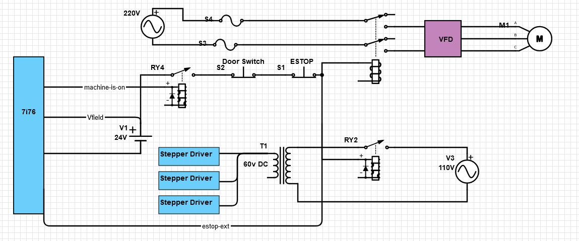
Ah, thanks a million! Comme ca?
Attachments:
Please Log in or Create an account to join the conversation.
- PCW
-
- Offline
- Moderator
-
Less
More
- Posts: 17991
- Thank you received: 5281
04 May 2021 23:38 #207904
by PCW
Replied by PCW on topic First steps for re-doing electrical
That looks good.
Please Log in or Create an account to join the conversation.
- rfrey
- Offline
- Junior Member
-
Less
More
- Posts: 20
- Thank you received: 3
05 May 2021 00:51 #207917
by rfrey
Replied by rfrey on topic First steps for re-doing electrical
Thanks, I appreciate the guidance.
My mill has a base cabinet that has a big opening in the back with a door. I was planning on putting the electronics on a panel and then attaching that to the side of the cavity with drawer slides.
Is there any reason the panel has to be metal? Can I use plywood or do I need a big grounded surface?
My mill has a base cabinet that has a big opening in the back with a door. I was planning on putting the electronics on a panel and then attaching that to the side of the cavity with drawer slides.
Is there any reason the panel has to be metal? Can I use plywood or do I need a big grounded surface?
Please Log in or Create an account to join the conversation.
- BeagleBrainz
-
- Visitor
-
05 May 2021 04:00 - 06 May 2021 01:25 #207925
by BeagleBrainz
Replied by BeagleBrainz on topic First steps for re-doing electrical
I’d use a metal plate and run a bonding strap to the main earth.
There could be a chance if you rely on the draw slides alone you may end up with different earth potentials.
A timber back plate would provide functionally no earth which would not be a good idea if a mains live wire became dislodged.
That’s just my two cents.
There could be a chance if you rely on the draw slides alone you may end up with different earth potentials.
A timber back plate would provide functionally no earth which would not be a good idea if a mains live wire became dislodged.
That’s just my two cents.
Last edit: 06 May 2021 01:25 by BeagleBrainz. Reason: Off topic
Please Log in or Create an account to join the conversation.
Time to create page: 0.249 seconds