Set up parallel port as input _ hardware
- Nordle
- Offline
- New Member
-

Less
More
- Posts: 5
- Thank you received: 0
24 May 2021 20:49 - 24 May 2021 21:00 #210101
by Nordle
Set up parallel port as input _ hardware was created by Nordle
Hey folks,
I added a second parallel port to my setup and would like to set it up with 13 inputs like in the picture.
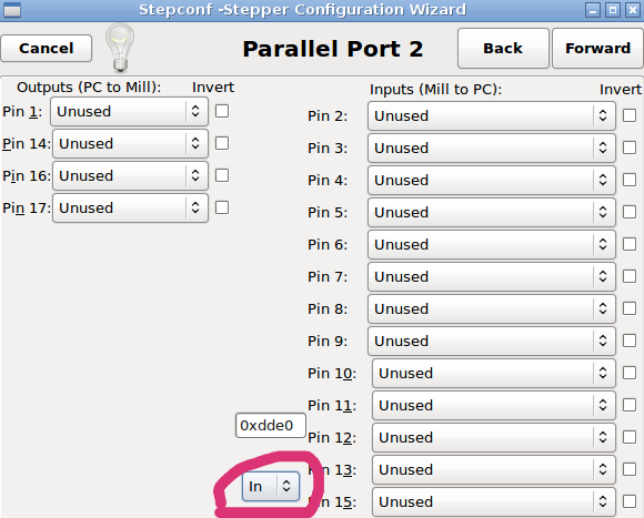
I made a machine configuration and checked the new parport in my hal configuration. When i short pin 2 for example to gnd the yellow indicator turns red for that pin. But does not turn back when i remove the connection. I do not understand how the parport works, does it need a pullup?
How would i wire a simple switch to one of the outputs/inputs? I also have some optocouplers i plan to use.
Thanks
I added a second parallel port to my setup and would like to set it up with 13 inputs like in the picture.
I made a machine configuration and checked the new parport in my hal configuration. When i short pin 2 for example to gnd the yellow indicator turns red for that pin. But does not turn back when i remove the connection. I do not understand how the parport works, does it need a pullup?
How would i wire a simple switch to one of the outputs/inputs? I also have some optocouplers i plan to use.
Thanks
Attachments:
Last edit: 24 May 2021 21:00 by Nordle.
Please Log in or Create an account to join the conversation.
- tommylight
-

- Offline
- Moderator
-

Less
More
- Posts: 21747
- Thank you received: 7433
24 May 2021 23:08 #210132
by tommylight
Replied by tommylight on topic Set up parallel port as input _ hardware
It is better to use the built in parallel port for inputs and the add on as outputs, this way even if the add on miss behaves = the machine will not move. If it fails to load as inputs the machine will move but the inputs will not work so the machine could crash, assuming the inputs are for limit switches.
The main reason for that is that most motherboards assign resources to add on cards automatically so the address might change at boot time, it did happen to me twice. This can be prevented in BIOS by setting the resources manually, but not all boards have that option.
And yes, most add ons will need pull up resistors on inputs.
Please Log in or Create an account to join the conversation.
- andypugh
-

- Offline
- Moderator
-
Less
More
- Posts: 19879
- Thank you received: 4643
24 May 2021 23:11 #210134
by andypugh
It might, it rather depends on the parport. And (unexpectedly) the mode it is configured in.
If your BIOS sees your parport, the configure it EPP. this shouldn't matter, but in some cases is increases current drive capacity. (Yes, I know, that makes no sense)
Does the pin ever come back?
Replied by andypugh on topic Set up parallel port as input _ hardware
I made a machine configuration and checked the new parport in my hal configuration. When i short pin 2 for example to gnd the yellow indicator turns red for that pin. But does not turn back when i remove the connection. I do not understand how the parport works, does it need a pullup?
It might, it rather depends on the parport. And (unexpectedly) the mode it is configured in.
If your BIOS sees your parport, the configure it EPP. this shouldn't matter, but in some cases is increases current drive capacity. (Yes, I know, that makes no sense)
Does the pin ever come back?
Please Log in or Create an account to join the conversation.
- Nordle
- Offline
- New Member
-
Less
More
- Posts: 5
- Thank you received: 0
25 May 2021 07:37 #210198
by Nordle
Replied by Nordle on topic Set up parallel port as input _ hardware
I just use 0 and 1 as parport base address. Pic is just from web.
Please Log in or Create an account to join the conversation.
- Nordle
- Offline
- New Member
-
Less
More
- Posts: 5
- Thank you received: 0
25 May 2021 07:41 - 25 May 2021 08:04 #210199
by Nordle
---
My question still is:
How would i wire a simple switch directly to the parport?
Replied by Nordle on topic Set up parallel port as input _ hardware
The pin comes back when connected to my breakout board i normally use on parport 0. Works as expected.It might, it rather depends on the parport. And (unexpectedly) the mode it is configured in.
If your BIOS sees your parport, the configure it EPP. this shouldn't matter, but in some cases is increases current drive capacity. (Yes, I know, that makes no sense)
Does the pin ever come back?
---
My question still is:
How would i wire a simple switch directly to the parport?
Last edit: 25 May 2021 08:04 by Nordle.
Please Log in or Create an account to join the conversation.
- BeagleBrainz
-

- Visitor
-

25 May 2021 08:04 - 25 May 2021 08:05 #210203
by BeagleBrainz
Replied by BeagleBrainz on topic Set up parallel port as input _ hardware
Use one of these, it keep you from pulling tour hair out and messing things up.
www.cnc4pc.com/bi-directional-parallel-port-interface-card.html
Or there is some generic info here: www.epanorama.net/circuits/parallel_output.html#circuithow
The section discussing inputs is halfway down the page.
www.cnc4pc.com/bi-directional-parallel-port-interface-card.html
Or there is some generic info here: www.epanorama.net/circuits/parallel_output.html#circuithow
The section discussing inputs is halfway down the page.
Last edit: 25 May 2021 08:05 by BeagleBrainz.
Please Log in or Create an account to join the conversation.
- Nordle
- Offline
- New Member
-
Less
More
- Posts: 5
- Thank you received: 0
25 May 2021 08:19 - 25 May 2021 08:32 #210204
by Nordle
Replied by Nordle on topic Set up parallel port as input _ hardware
Thanks but the bob you suggest is not in my budget:/ Could this one work instead: € 13,86 12%OFF | 1PCS CNC parallel port interface board photoelectric isolation (support KCAM4, EMC2/linuxcnc) in stock
a.aliexpress.com/_vcLylB
But i'd still prefer to go without a bob. Gonna read trough the link you suggested, maybe i can figure it out.
Thanks
a.aliexpress.com/_vcLylB
But i'd still prefer to go without a bob. Gonna read trough the link you suggested, maybe i can figure it out.
Thanks
Last edit: 25 May 2021 08:32 by Nordle.
Please Log in or Create an account to join the conversation.
- BeagleBrainz
-
- Visitor
-
25 May 2021 08:36 #210205
by BeagleBrainz
Replied by BeagleBrainz on topic Set up parallel port as input _ hardware
Doesn't give much info regarding which pins are configured as input or output.
Best thing about a BoB it provides some sort of protection to the parallel port.
Best thing about a BoB it provides some sort of protection to the parallel port.
Please Log in or Create an account to join the conversation.
- Nordle
- Offline
- New Member
-
Less
More
- Posts: 5
- Thank you received: 0
25 May 2021 08:44 #210207
by Nordle
Replied by Nordle on topic Set up parallel port as input _ hardware
I'll just try to diy it with some optocouplers for now:)
Please Log in or Create an account to join the conversation.
- andypugh
-
- Offline
- Moderator
-
Less
More
- Posts: 19879
- Thank you received: 4643
25 May 2021 21:31 #210263
by andypugh
Replied by andypugh on topic Set up parallel port as input _ hardware
You can typically change the state of a parallel port pin by connecting it to one of the GND pins on the same connector.
If using optos, then NPN wiring to parport GND pins will work.
If using optos, then NPN wiring to parport GND pins will work.
Please Log in or Create an account to join the conversation.
Time to create page: 0.225 seconds